Owner’sManual with Installation Instructions Banks PowerPack® System Ford 460 EFI Class-A Motorhomes Ford Chassis, Non-Catalytic Converter THIS MANUAL IS FOR USE WITH SYSTEMS 49090 & 49093 Gale Banks Engineering 546 Duggan Avenue • Azusa, ca 91702 (626) 969-9600 • Fax (626) 334-1743 Product Information & Sales: (888) 635-4565 Customer Support: (888) 839-5600 Installation Support: (888) 839-2700 bankspower.com ©2012 Gale Banks Engineering 05/15/12 PN 96344 v.3.
general installation practices Dear Customer: Your new Banks PowerPack® is a unique combination of air intake and exhaust components designed to make the most of your engine’s power potential. By removing intake and exhaust restrictions, providing cooler intake air, and tuning the exhaust to create a scavenging effect, your engine can produce more power at a higher level of efficiency.
Factory exhaust manifold bolt removal Because of a condition inherent in the factory design, the exhaust manifolds may crack the manifold-to-head bolts as manifolds undergo changes in length from expansion and contraction. In some cases, these forces may also crack the exhaust bolt bosses on the cylinder head. Cracked bolts will not show any external damage, but bolt heads may break off upon removal. We recommend that you do the following to minimize the possibility of broken manifold bolts. 1.
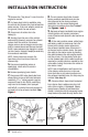
installation Instruction 1. Remove the “dog house” cover from the engine for access. 2. If a heavy duty hoist is available, raise the vehicle and remove the front wheels for easier access. If the rear wheels remain on the ground, block the rear wheels. 3. Disconnect all cables from the battery(s). 4. Starting from the rear of the vehicle and working forward, remove the exhaust system from the vehicle. Disconnect oxygen sensor wire at oxygen sensor plug (plug is located about two feet up the wire loom).
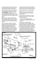
front axle) from the bottom of the frame rail. Reinstall the bump stop bracket while bolting the brake line heat shield supplied in the PowerPack kit under the nuts securing the bracket to the frame rail (see Figure 3). Install a 1⁄4–28 x 1” hex bolt, two SAE washers and a 1⁄4–28 locknut through the heat shield and into a corresponding hole on the engine mount bracket. 12. Inspect the cylinder head exhaust flange surfaces. Remove any loose carbon, rust, old gasket material, etc.
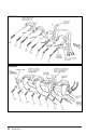
FIGURE 4 FIGURE 5 6 96444 v.3.
TorqueTubes. Instructions are provided, however, to allow for reinstallation should you decide to do so. The tabs that attach the spark plug boot heatshields must be bent to line up with the bolt holes in the manifold flange. Adjust the tabs as required so spark plugs may be serviced. End tabs on some heat shields may not line up with bolt holes. In this case use center mounting tabs only. B. Spacers are used with some bolts to mount the ignition coil bracket, emissions control bracket and heat shield.
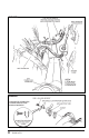
FIGURE 6 FIGURE 7 AIR INJECTION CONNECTION AT REAR OF RIGHT-HAND EXHAUST MANIFOLD 8 96444 v.3.
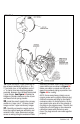
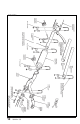
FIGURE 8 19. Install the Banks Y-pipe. assembly to the exhaust manifolds using four 3⁄8–16 x 2” hex bolts, four 3⁄8 SAE washers and a 2 1 ⁄2” U-clamp. Use two doughnut gaskets, provided, between the manifold outlets and Y-pipe flanges. See Figure 9. Rotate the flanges to provide clearance to the oil pan and lower bolt of spring shackle. 20. Install the small, straight-thru primary muffler to Y-pipe. Use 3” U-clamp. Install hanger rod on Y-pipe into factory hanger. 21.
FIGURE 9 10 96444 v.3.
FIGURE 10 22. Install 28” intermediate pipe in outlet of primary muffler. Install 3” U-clamp to secure pipe in muffler. Install 3” hanger clamp on intermediate pipe to support muffler. See Figure 9. 23. The Ford Class “A” Motorhome chassis is supplied in several wheelbase lengths. The standard length is 178” wheelbase. Longer wheelbase coaches will require an additional extension pipe.
FIGURE 11 26. Install intermediate pipe heatshield on intermediate pipe between primary and secondary mufflers. Heatshields install with the shield above the pipe, to protect the coach floor. Because the location of factory pipe hangers will vary, the installer must provide a notch in the heat shield to clear the hanger rod on the U-clamp hanger. See Figure 12. Make two saw cuts through the folded lip of the heat shield, one inch into the flat section beyond the fold line.
FIGURE 12 the tailpipe as shown in Figure 11. The heat shield should be installed in the same fashion as mentioned in the preceding steps. Tip may be slid in or out on the tailpipe to match the body width. If the tailpipe must be shortened to position the tip near the coach body, cut the tailpipe to place it 1 to 2 inches within the outside end of the tailpipe tip. This will minimize any heat discoloration of the chrome plating on the tailpipe tip.
Banks Ram-Air System FIGURE 13 TRIM FRONT OF BANKS SUPERSCOOP TO MATCH ANGLE OF GRILLE The Banks PowerPack cold air induction components are designed to extend the factory air intake path so that cooler outside air can be picked up from directly behind the vehicle’s grille. These components include a molded Banks Super-Scoop™, 4” diameter flexible tubing, Ram-Air Filter Cover and installation hardware. Figure 13 shows a typical hook-up of the air intake components as they tie to the factory system.
31. Once a location has been determined for the Super-Scoop, mount it using one of the methods outlined below. FIGURE 14 The Banks Super-Scoop may be mounted by several means. If the grille consists of horizontal bars or a perforated metal screen heavy enough to support the inductor, it may be secured using four 14” nylon cable ties, provided, slipped through the ears on the Scoop and through the grille. See Figure 14.
Cleaning and oiling banks ram-air filter Notification 3. cleaning hints The Banks Ram-Air Filter comes pre-oiled and no oiling is necessary for initial installation. Use Banks Ram-Air Filter cleaning system (part #90094), available from Gale Banks Engineering to service the Air Filter. Follow the instructions included with the cleaning system to clean and re-oil your Banks Ram-Air Filter. Use only Banks air-filter cleaner.
7. oiling hints 9. do not discard Never use a Banks Ram-Air filter without oil (the filter will not stop the dirt without the oil). Use only Banks Ram-Air filter oil. Banks air-filter oil is a compound of mineral and animal oil blended with special polymers to form a very efficient tack barrier. Red dye is added to show just where you have applied the oil. Eventually the red color will fade but the oil will remain and filter the air. NEVER USE Automatic Transmission Fluid. NEVER USE Motor Oil.
Ford 460 EFI Class-A Motorhome PowerPack System Bill Of Materials Component Part # Qty Assembly, Hanger Clamp, 3” 52694 1 Assembly, Hanger Clamp, 3 1/2” 52695 1 Bolt, 1/4-28 x 1”, Hex 91140 1 Bolt, 3/8” 16 x 2”, Hex 91466 4 Bolt, 5/16” 24 x 5/8” 91251 2 Bolt, Manifold, 3/8” 16 x 1 1/4”, 12 point 91952 12 Bolt, Manifold, 3/8” 16 x 2”, 12 point 91953 2 Bolt, Manifold, 3/8” 16 x 3”, 12 point 91955 2 Clamp, Cable, 1/2” dia.
Component Part # Qty Pipe, Intermediate, 3 x 28” 52673 1 Pipe, Y-Pipe Assembly 52135 1 Spacer, Exhaust Manifold Bolt, 3/8 x 5/8” 26096 2 Spacer, Exhaust Manifold Bolt, 3/8 x 1 3/4” 35295 2 Tie, Cable, 8” Black 62010 5 Washer, 5/16”, Circle Lock 91205 4 Washer, 1/4”, SAE 91102 2 Washer, 3/8”, SAE 91402 20 Warranty Statement 96363 1 Wire Extension, O2 Sensor 62200 1 Wire, Steel Tie, Heatshield 26013 4 Card, Product Registration 96392 1 Decal, Card. E.O.
FIGURE 15 Gale Banks Engineering 546 Duggan Avenue • Azusa, ca 91702 (626) 969-9600 • Fax (626) 334-1743 Product Information & Sales: (888) 635-4565 Customer Support: (888) 839-5600 Installation Support: (888) 839-2700 bankspower.