
Owners manual


4 96444 v.3.0
1.
R
emove the “dog house” cover from the
engine for access.
2.
If a heavy duty hoist is available, raise
the vehicle and remove the front wheels for
easier access. If the rear wheels remain on
the ground, block the rear wheels.
3. Disconnect all cables from the
battery(s).
4. Starting from the rear of the vehicle
and working forward, remove the exhaust
system from the vehicle. Disconnect
oxygen sensor wire at oxygen sensor plug
(plug is located about two feet up the wire
loom). Leave exhaust pipe hangers in place
on the chassis. Remove headpipe assembly
from exhaust manifolds.
NOTE: Some joints may require the
heat from a torch to loosen them for
disassembly.
5.
Disconnect sparkplug wires at
sparkplugs. Label wires to assist in
reinstallation.
6.
Remove sparkplug heat shields.
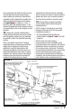
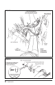
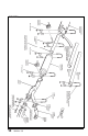
7.
Disconnect EGR valve feed tube from
elbow fitting at rear of left hand exhaust
manifold. A 1
1
⁄
16
” tubing wrench may be
required (Snap On No. RX34), and fitting
may have to be heated, then sprayed
with WD40, or similar lubricant to assist in
removal from the exhaust manifold. See
Figure 1.
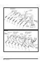
8.
The air injection feed tube for each
factory exhaust manifold must also be
disconnected at the factory exhaust
manifolds. Use the same heating and
lubrication procedure described in step 7.
See Figures 1 and 2.
9.
Remove exhaust manifolds from engine.
Unbolt ignition coil bracket, emissions
control bracket and dipstick tube bracket as
required.
10.
If the main positive power cable (large
red battery cable) crosses over from the
frame to the starter motor adjacent to
the exhaust manifold area, disconnect it
at the stud on the starter motor. Re-route
the cable to the starter motor by feeding
the cable between the side engine mount
and the oil pan. Cut the plastic cable ties
on the forward part of the cable bundle as
required to provide slack as needed for the
new cable routing. Reconnect the cable at
the starter motor.
NOTE: Not all installations will require this.
If the battery cable does not cross over
from the frame to the starter adjacent to
the exhaust manifold area, this step may be
omitted. See step 16.
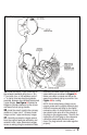
11.
Remove fabric heat shield material
from frame that is adjacent to the left
side of the engine, if equipped. (Many
motorhome chassis do not have this
shield.) Unbolt the left front spring bump
stop bracket (located directly above the
FIGURE 1 FIGURE 2
INSTALLATION INSTRUCTION