owners manual with installation instructions dynafact ® boost GAUGE this manual is for use with systemS 64050-64054 gale banks engineering 546 duggan avenue • azusa, ca 91702 (626) 969-9600 www.bankspower.com ©2009 gale banks engineering 12/18/09 p.n. 96327 v.3.
GENERAL INSTALLATION PRACTICES This manual is an installation guide for all 1. Banks DynaFact boost gauges. For ease of installation and to determine what additional tools or materials you will need, read the entire 8–page manual before starting any work. NOTE there are portions of the installation procedure and certain illustrations matched to specific vehicle types. For proper installation, select the text and illustrations that closest correspond to your vehicle.
INSTALLATION PROCEDURE GAUGE PANEL INSTALLATION Choose a suitable location under the lower edge of the dash panel for mounting the instrument panel, or on top of the dash for the molded instrument console. Be certain the instruments can be viewed conveniently by the driver. Chevrolet/GMC 6.5L diesel with factory turbo — Loosen the hose clamp on the compressor discharge of the turbocharger. Remove the connecting strap between turbocharger and air inlet casting.
TUBING INSTALLATION All gauge tubing should be routed away from heat sources such as exhaust manifolds or piping, and away from sharp edges. Avoid sharp bends or kinks. Secure the tubing to other tubing inside the engine compartment with cable ties. Ford/Navistar 6.9L/7.3L IDI diesel with Banks Sidewinder turbo — Locate the 1⁄8" NPT threaded hole in the pressure chamber. Install the straight fitting provided into the threaded hole with Teflon threadsealer. Ford/Navistar 7.
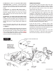
FIGURE 3 FORD/NAVISTAR POWER STROKE 7.3L GAUGE INSTALLATION Install the gauge through the panel or console using the U-clamp and two hex nuts provided with the gauge. ground. Incorrect wiring will result in a non-working LED. See Figure 4. If more than one gauge is being used, the wires from other 4-pin connectors may be doubled up in the connectors. No more than two wires should be in either end of the butt connector. Route the red wire to the fuse panel.
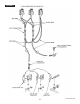
FIGURE 4 6 P.N. 96327 v.3.
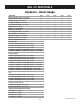
BILL OF MATERIALS DynaFact – Boost Gauge COMPONENT 64050 64051 64052 64053 64054 ✓ – – – – – ✓ ✓ ✓ ✓ ✓ ✓ – – ✓ ✓ ✓ ✓ ✓ ✓ – – – – ✓ ✓ ✓ ✓ ✓ – – – – – – – – – – – – – ✓ ✓ – – – – ✓ ✓ ✓ ✓ ✓ ✓ ✓ ✓ ✓ ✓ ✓ ✓ BOOST GAUGE 0-15 psi p/n 63435 BOOST GAUGE 0-50 psi p/n 63436 FITTING, straight p/n 92301 FITTING, 90° elbow p/n 92303 (2) FITTING, 90° elbow p/n 92303 FITTING, tee p/n 92011 HOSE, 11 1⁄2' p/n 94445 HOSE, 55' p/n 94445 (2) CLAMP, spring band p/n 92877 (6) CABLE TIE, 5" p/n
gale banks engineering 546 duggan avenue • azusa, ca 91702 (626) 969-9600 www.bankspower.