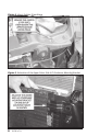
Owner’sManual with Installation Instructions Banks Techni-Cooler Charge Air Cooler Assembly ® 2003 to 2007 Dodge 5.9L Cummins (24-valve) ISB Pickup Trucks Use with system p/n 25980, 25981 Gale Banks Engineering 546 Duggan Avenue • Azusa, ca 91702 (626) 969-9600 • Fax (626) 334-1743 Product Information & Sales: (800) 438-7693 bankspower.com ©2010 Gale Banks Engineering 08/09/10 PN 96785 v.7.
Also Available from Banks Power 03-07 Dodge 5.9L BigHead® Wastegate Monster Exhaust Banks iQ Banks Bullet™ Banks Billet™ Torque Converter DynaFact ® Instrumentation ® Monster-Ram Advanced Diesel Tuners Banks Brake® Banks Ram-Air ® Intake Techni-Cooler® System Super-Scoop ® Banks iQ System (P/N 61148-61149) - 5” touchscreen interface that can control the Banks Diesel tuner on the fly.
Banks Billet Torque Converter (P/N 72515) - Higher torque capacity over stock - Lockup clutch is slip-resistant so transmission fluids stay cooler and transmission life is prolonged.
General Installation Practices Dear Customer, If you have any questions concerning the installation of your Banks Techni-Cooler, please call our Technical Service Hotline at (888) 839-2700 between 7:00 am and 5:00 pm (PT). If you have any questions relating to shipping or billing, please contact our Customer Service Department at (888) 839-5600. Thank you. 1. Before starting work, familiarize yourself with the installation procedure by reading all of the instructions. 2.
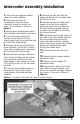
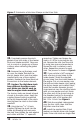
Intercooler Assembly Installation 1. Disconnect the negative battery cables from both batteries 2. Disconnect the Inlet Air Temperature/ Pressure Sensor connector located on the air box cover. The connector is shown in Figure 1. 3. Remove the nut that fastens the air filter housing to the radiator cross brace. 4. Loosen the hose clamp that secures the air inlet duct to the turbocharger inlet. Disconnect the inlet duct from the turbocharger. 5. Remove the air box and inlet duct as an assembly.
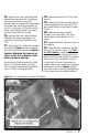
Figure 2. Upper Radiator Cross Brace Figure 3. Relocation of the Upper Driver Side A/C Condenser Mounting Bracket 6 96785 v.7.
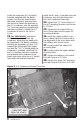
15. Remove the hex head bolts that attach the lower two A/C condenser mounting brackets to the CAC. Remove the torx head bolts that fasten the lower two mounting brackets to the A/C condenser. Discard the stock lower mounting brackets, but retain the torx head bolts for re-use. 16. Remove the hex head bolt that attaches the upper passenger A/C condenser mounting bracket to the CAC. 17. Swing the A/C condenser upward as shown in Figure 4, then out away from the vehicle as shown in Figure 5.
Install the lower two A/C mounting brackets supplied with the Banks system. Use the torx head screws that were previously removed from the vehicle to fasten the brackets to the A/C condenser. Use the supplied 5⁄ 16” bolts and washers supplied with the Banks system to fasten the A/C condenser mounts to the TechniCooler. 23. For 2006 Models, remove all of the factory brackets from the condenser, retain the torx head bolts for reassembly. The Banks condenser brackets are stamped such that “R.U.
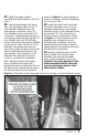
31. Tighten the upper radiator shown in Figure 6 to avoid clearance issues. The clamps should be tightened to 5 ft-lbs (60 in-lbs). 32. Install the passenger side boost 33. Install the driver side boost tube. mounting bolts and torque to 8 ft-lbs (96 in-lbs). tube. The passenger side uses a 2.75 inch diameter straight hose at the turbocharger connection, and a 3.5 inch diameter hump hose at the CAC connection. The passenger side tube is most easily installed by placing the 2.
Figure 7. Orientation of the Hose Clamps on the Driver Side. 35. Completely remove the stock gaskets from both sides of the heater block and intake manifold. Take care not to scratch or gouge any of these surfaces when removing the gasket material. 36. Remove the rag that was used to cover the intake. Reinstall the electric heater block onto the intake manifold with one of the supplied gaskets. Reattach the three electrical connections to the heater element. 37.
passenger side studs. The washers should be installed in a twisting motion to prevent tearing their sealing element. Install the supplied 5⁄ 16” flat washer on all studs, then fasten with the supplied 5⁄ 16-24 nylock nuts. The nuts should be tightened to 12 ft-lbs (144 in-lbs). An exploded view of the High-Ram assembly is shown in Figure 9. 42. Gently bend the engine oil dipstick tube to it’s mounting location on the High Ram as shown in Figure 9.
Figure 9. Exploded view of the High-Ram assembly Gale Banks Engineering 546 Duggan Avenue • Azusa, ca 91702 (626) 969-9600 • Fax (626) 334-1743 Product Information & Sales: (800) 438-7693 bankspower.