
User guide


35. Completely remove the stock
gaskets from both sides of the heater
block and intake manifold. Take care
not to scratch or gouge any of these
surfaces when removing the gasket
material.
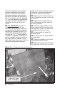
36. Remove the rag that was used
to cover the intake. Reinstall the
electric heater block onto the intake
manifold with one of the supplied
gaskets. Reattach the three electrical
connections to the heater element.
37. Caution: The High Ram studs
have different threads on each
end. Make sure the M8 ends go
into the engine intake manifold.
The shorter studs are placed inboard
closest to the valve cover. Apply the
supplied thread locking compound
to the M8 threaded end of the studs.
Hand tighten the studs to the intake
manifold.
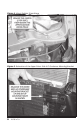
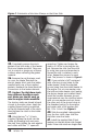
38. Using the two
5
⁄16”-24 nuts
supplied, tighten the studs into the
intake by threading both nuts onto
the stud, then tighten the nuts against
each other with two
1
⁄2” open end
wrenches. Tighten and torque the
stud to 3-5 ft-lbs by turning the top
nut. Remove the nuts from the stud
by using two open end wrenches to
loosen the nuts in relation to each
other. Repeat the process for each
stud. The process is shown in Figure 8.
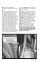
39. If your vehicle is NOT equipped
with a factory ground strap on the
intake heater, install the supplied
ground strap from the intake heater to
the engine. Put a 6-mm washer onto
the bottom intake heater stud, leaving
the factory heater nut installed. Next,
install the smaller diameter ground
strap terminal over the stud and retain
with a 6-mm washer and nut. Route
the other end of the ground strap to
the threaded section on the engine
and retain with a SAE washer and
M8-1.25x 16 bolt. See Figure 8.
40. Slide the supplied intake gasket
over the four studs, then slide the
High-Ram over the studs.
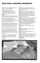
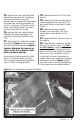
41. Install the supplied Stat-O-Seal
washers on the two driver side (longer)
studs. Driver side studs are longer than
Figure 7. Orientation of the Hose Clamps on the Driver Side.
10 96785 v.7.0