Owner’sManual with Installation Instructions Banks Brake with CBC/SmartLock® Exhaust Brake System 2004-2007 Dodge Cummins ISB Pickup Trucks THIS MANUAL IS FOR USE WITH CBC/SMARTLOCK EXHAUST BRAKE SYSTEMS 55225, 55226, 55229 Gale Banks Engineering 546 Duggan Avenue • Azusa, CA 91702 (626) 969-9600 • Fax (626) 334-1743 Product Information & Sales: (888) 635-4565 bankspower.com ©2012 Gale Banks Engineering 03/16/12 PN 97055 v.8.
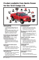
Product available from Banks Power for the ‘03-07 Dodge 5.9L BigHead® Wastegate Monster Exhaust Banks iQ Banks Bullet™ Banks Billet™ Torque Converter DynaFact ® Instrumentation ® Monster-Ram Advanced Diesel Tuners Banks Brake® Banks Ram-Air ® Intake Techni-Cooler® System Super-Scoop ® Banks iQ System (P/N 61148-61149) - 5” touchscreen interface that can control the Banks Diesel Tuner on the fly.
Banks Billet Torque Converter (P/N 72515) - Higher torque capacity over stock - Lockup clutch is slip-resistant so transmission fluids stay cooler and transmission life is prolonged.
Limitation of Warranty Gale Banks Engineering Inc. (hereafter “SELLER”), gives Limited Warranty as to description, quality, merchantability, fitness for any particular purpose, productiveness, or any other matter of SELLER’s product sold herewith. The SELLER shall be in no way responsible for the product’s open use and service and the BUYER hereby waives all rights except those expressly written herein. This Warranty shall not be extended or varied except by written instrument signed by SELLER and BUYER.
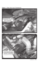
Figure 1 Driver Side, Top of Transmission Figure 2 Engine Compartment Driver Side 97055 v.8.
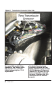
Figure 3 Transmission Connectors Driver Side For some 2004 models, if the diameter of the Turbine Outlet Pipe (T.O.P) is 3½“, call Gale Banks Engineering for a T.O.P replacement. 6 97055 v.8.0 If a Banks Tuner has been previously installed call Gale Banks Technical Service at (888) 839-2700 between 7:00am and 5:00pm (PST) to make sure you have a compatible version of the tuner. Otherwise the CBC/ SmartLock will not function properly.
General Installation Practices Dear Customer, Your new Banks Brake with CBC/ SmartLock is a uniquely designed exhaust brake with electronic controls, designed to achieve the optimum level of braking from your vehicle’s engine. If you have any questions concerning the installation and operation of the Banks CBC/ SmartLock Exhaust Brake, please call our Technical Service Hotline at (888) 839-2700 between 7:00 am and 5:00 PM (PST).
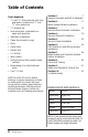
Table of Contents Tools Required: • 1⁄ 2” and 3⁄ 4” drive ratchets with inch and metric sockets and 1⁄ 2” and 3⁄ 8” drive extension • 1⁄ 2” breaker bar • Inch and metric combination or open-end wrenches • Standard screwdriver • Clean shop towels or rags • Pliers • Utility knife • Electric drill Section 1 . . . . . . . . . . . . . . . . . . . . .7 General Assembly and Bill of Materials Section 2 . . . . . . . . . . . . . . . . . . . . 11 Banks Exhaust Brake Installation Section 3 . . . . . . . . . . . .
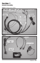
Section 1 General Assembly Figure 4 Wiring Harness 55406 Figure 5 97055 v.8.
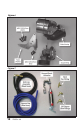
Figure 6 Figure 7 10 97055 v.8.
Bill of Materials Description P/N Kit 55225 Kit 55226 Kit 55229 Assembly, Brake Housing 55045 1 1 1 Vacuum Pump 55176 1 1 1 Bracket, Vacuum Pump 55177 1 1 1 Vacuum Boost Actuator 55071 - - 1 Hex Bolt, Washer Head, Black, M8x1.25 x 25mm 91809 3 3 3 Hex Bolt, Washer Head, Black, M8x1.25 x 40mm 91815 4 4 4 Vacuum Solenoid 55138 1 1 1 91742 1 1 1 Hex Bolt, Zinc, M6x1.00 x 25mm 91102 1 1 1 Nut, Nylock, M6 x 1.
Bill of Materials (continued) Description Hose, 1/4” P/N Kit 55225 Kit 55226 Kit 55229 9 ft 94121 - - 1 Hose, 5⁄ 16” 5 ft 94129 1 1 1 94450 - - 1 92121 - - 1 Brass Tee Fitting, 1/4” 92243 - - 2 Spring Band Clamp, 3/8” 92875 - - 5 Belt, Serpentine, Vacuum Pump 65120 1 1 1 Vent Hose Assembly Hose Fitting, 1/8” NPT x 90-Degree Elbow 3/16”, Urocal, Banks Power, Small 96009 2 2 2 Cable Ties, 7” 62010 25 25 25 Module Bracket Kit- Optional (All) 55298 Kit # 55229
Section 2 Banks Exhaust Brake Installation 1. As a precaution, disconnect the ground of the battery (if there is more than one battery, disconnect both grounds). Note: It may be necessary to loosen or remove the exhaust support from the transmission to provide extra clearance. 2. Push the exhaust pipe to the rear of the vehicle slightly to allow the elbow to be removed. Slide the elbow towards the rear of the vehicle to allow the alignment pins in the turbo to come free.
2006-07 trucks proceed to Step 5. 2004-05 proceed to Step 8. 5. For 2006-07 trucks, the heater core tube that is above the exhaust pipe will have to be replaced with Banks Heater Core Tube to provide additional clearance for the Brake. 6. Drain the radiator fluid into a suitable container to be re-used. Loosen the hose clamps and remove the heater hoses from the heater core tube. Remove the two (2) nuts and one (1) bolt that attach the coolant line to the engine.
Figure 10 Driver Side Figure 11 Exhaust Brake Orientation 97055 v.8.
Figure 12 11. Slide the V-clamp that is on the Brake assembly onto the turbo outlet. Make sure that the flanges on the Banks Brake and the turbo’s outlet are centered in the V-clamp. Loosely tighten the clamp. 12. Clamp the Brake and exhaust pipe together with the V-clamp that was placed over the exhaust. Note: If the exhaust support was removed, a block of wood on a jack or a friend may help in lining up the exhaust pipe to the Banks Brake easier. 16 97055 v.8.0 13. Tighten the V-clamps. 14.
Section 3 Vacuum Boost Actuator Installation If installing kit 55229 continue with this section, For kits 55225 and 55226 skip to Section 4. Note: The following instructions assume that a Banks Brake System has been previously installed on the vehicle. 1. Locate the two (2) supplied rubber 1/4” hoses for the Vacuum Boost Actuator assembly (Black and Blue hose). Route one end of the rubber hoses from the top left side of the engine compartment down to the left side of the transmission.
Figure 14 Figure 15 18 97055 v.8.
Figure 16 7. Remove the mounting bolt from the transmission case and install the line pressure boost actuator and bracket as shown in Figure 16. Temporarily finger-tighten the bolt to allow for adjustment. 8. Slide the actuator control lever over the throttle valve shaft and tighten the bolt. Re-attach the return spring to the transmission case actuator control bracket as shown in Figure 17. Re-attach the kick-down cable removed in step 4.
Figure 17 10. Locate two spring band clamps and slide over the rubber hose that were routed down to the left side of the transmission in step 1. 11. Locate the blue hose, this hose will connect to the vacuum solenoid in Section 4, and insert the hose in the rear 90-degree barb fitting. Secure the hose to the fitting by sliding the spring band clamp into place. See Figure 18. 12.
Figure 18 Vacuum Boost Actuator Hose connections Figure 19 Vent Line with Breather Assembly, Left Side Engine Compartment 97055 v.8.
Section 4 Vacuum Solenoid Installation 1. Locate the rail along the rear of the engine compartment. Remove the push-in retainer that is closest over the exhaust brake with an upholstery tool or screw driver. 2. Locate the supplied Banks Vacuum Solenoid along with it’s 1⁄4” split and flat washers, M6 x 1.0mm x 25mm bolt, and M6 x 1.0 nut. Slide the 1⁄4” flat washer onto the bolt and install the Solenoid at the location where the push-in retainer was previously removed. See Figure 20 & 21.
Figure 21 For models with no Throttle Valve Assembly (some 2004) Figure 22 97055 v.8.
Section 5 Vacuum Pump Installation 1. Use a 1⁄ 2” ratchet or breaker bar to loosen the tensioner pulley to create slack on the drive belt. Remove the factory drive belt. 2. Locate the Banks Vacuum Pump and attach it to the supplied Vacuum Pump Bracket using the three M8 x 1.25 x 25mm supplied bolts. Torque them to 18 ft-lbs (25 N*m). See Figure 23. 3. With the four supplied M8 x 1.25 x 40mm bolts, mount the Vacuum Pump assembly to the rear of the gear housing (Figure 24).
Figure 24 Figure 25 97055 v.8.
Section 6 CBC/SmartLock and Wiring Harness Installation 1. Remove the fuse box cover, located in the front driver’s side of the engine compartment. Locate mini-fuse #50 for 2004-05 trucks (Figure 26) or #28 for 2006-07 trucks (Figure 27) and remove it. 2. Install the mini-blade fuse tap onto the removed mini fuse as shown in Figure 28. Re-install the mini fuse with the attached blade tap into fuse box. For 2004-05 trucks, install the fuse tap in the #50 spot closest to the firewall as seen in Figure 26.
Figure 27 2006-07 Models Figure 28 Fuse Tap Installation 97055 v.8.
Figure 29 2004-2005 Models Figure 30 2006-07 Models 28 97055 v.8.
Figure 31 Ground Wire Attachment Location Figure 32 All Models CBC Smartlock Mounting Location 97055 v.8.
Figure 33 Optional Bracket P/N 55299 Shown 4. Attach the Ground wire (Black wire with ring terminal) to an existing bolt by removing the existing bolt and sliding the ring terminal over the bolt. Re-install the bolt. Use Figure 31 as an example location on the driver’s side fender. Note: Make sure your ground location is clean from dirt, grease and corrosion or the Banks CBC/SmartLock may not function properly. 5.
Figure 34 All Models Vacuum Solenoid Connection Location 8. 11. 9. Locate the connector for the Vacuum Solenoid on the Banks Wiring Harness. Route the wire to Vacuum Solenoid along the hose connected to the Solenoid and plug in the connector to the Solenoid as seen in Figure 34. Secure the wire and vacuum hose to the factory wiring harness with cable ties. Locate the factory C108 connector on the driver side of the transmission.
Figure 35 Left side of transmission Figure 36 Location of Rubber Grommet in Engine Compartment 32 97055 v.8.
Figure 37 In Cab Rubber Grommet If installing kit 55229, Locate the factory C109 connector on the driver side of the transmission. There will be three connectors connected on the left side of the transmission. Disconnect the connector farthest to the left of all three connectors. See Figure 35. Disconnect the C109 connector by sliding the locking tab out and press the locking clip while removing the connector.
Figure 38 OBD II Interface Cable CAUTION: Pull gently to avoid damage to the Wiring Harness Connectors or wires. Always pull on the Wiring Harness housing rather than the wires themselves. Trucks with a Banks Diesel Tuner skip to Note at end of step 16. 15. Locate the Banks OBD II Interface Cable in your kit. Connect the red OBD II Male Connector on the Banks OBD II Interface Cable to the vehicle’s OBD II female connector.
Figure 39 97055 v.8.
Section 7 Brake Enable and Overdrive Disable Switch Installation. CAUTION: Do not use force when working on plastic parts. Permanent damage to the part might result. panel (IP) next to the steering column (Figure 40) or location #2, on the knee panel above the brake release (Figure 41). Notes: Before drilling, confirm that there is adequate room for the Brake Enable and Overdrive Disable Switches and wires behind the dash. Make sure wires or obstructions are cleared from the drilling area.
Figure 41 Location #2- Late 2004 thru 2005 models 3. Remove the cluster bezel by first removing the two (2) screws at the top. Gently pull on it and disengage all the clips that attach the bezel to the dash. Retain the screws for reinstallation. 4. Cut out the supplied template (Figure 48) and align the template onto the front of the cluster bezel by placing its left edge against the cluster rib, and it’s bottom edge against the cluster bottom edge. Use masking tape to securely hold down the template.
Figure 42 Late 2004 thru 2005 models Figure 43 Late 2004 thru 2005 models 38 97055 v.8.
2006-2007 Switch install 9. Remove the lower dash knee panel from the vehicle by removing the two (2) screws at the bottom corners of the panel (retain for re-installation). There are also two (2) retaining clips located at the top corners of the panel, which hold the panel in place. These clips can be released by gently pulling on the corners of the panel. Use caution to avoid damaging the panel during removal.
Figure 45 2006 Models Power Adjustable Pedal Switch Location Notes: It is important that the hole is drilled as close as possible to the recommended location. The switch may not clear the instrument panel structure if the hole is shifted to another location. A pilot hole may be drilled first if a Unibit is unavailable. Use a drill bit smaller than 1/2”. 12. Align the Banks CBC/SmartLock Enable Switch label and the Overdrive Disable label over the previously drilled hole.
Figure 46 Brake Enable Switch Figure 47 Overdrive Disable Switch 16. Remove the chrome bezel nut from the Switch shaft. Insert the Switch shaft into the hole that was drilled in the dash panel. Re-install the chrome bezel nut. 17. Reconnect any electrical connectors and re-install the instrument panel(s). 19. Route all wiring away from any pedals or other moving components. Using the supplied cable ties, secure the wiring under the dash.
Section 8 Functional Testing The Banks Brake with CBC/SmartLock has been designed for your truck. It features: • Improved torque convertor control when in the factory’s Tow/Haul mode. • Overdrive Disable capability for towing. • Quicker engine warm-ups. • Compatible with cruise control. • Compatible with Banks Tuners. Note: The following testing should be performed only after the vehicle has been allowed to COMPLETELY COOL.
Section 9 Safety and Operation/ Driving Tips CAUTION: Your Banks Brake is NOT a substitute for the hydraulic brakes on your truck. The device will not correct or compensate for improperly maintained hydraulic brakes. Also, please be aware that your Banks Brake is not designed to be used as a parking brake or to bring your vehicle to a complete stop.
Section 10 Troubleshooting Your Banks Brake CBC/SmartLock is equipped with diagnostic features that will detect and display certain errors. If the Banks Brake does not pass the FUNCTIONAL TESTING or ceases to function properly, re-check all the connections per the installation instructions. Make sure that electrical connections are tight and secure and that the vacuum hoses are not kinked or pinched.
other end connected to the Vacuum Pump. Make sure the truck is in park and start the engine. Measure the vacuum at 1900 RPM. The Pump should generate a minimum of 10 psi (20.4” Hg) of vacuum. Replace the Vacuum pump if necessary. After testing, turn off the engine and disconnect the vacuum gauge and reconnect the 5⁄ 16” hose to Port 1 on the Vacuum Solenoid.
This Page Intentionally Left Blank 46 97055 v.8.
Figure 48- 2004-2005 Model Template Location #1 2004-2005 Model Template Figure 49- 2004-2005 Model Template Location #2 2004-2005 Model Template 97055 v.8.
This Page Intentionally Left Blank 48 97055 v.8.
Figure 50- 2006-07 Model Template 2006-07 Model Template Figure 51- 2006-07 Model Template 2006-07 Model Template 97055 v.8.
Notes 50 97055 v.8.
Notes 97055 v.8.
Gale Banks Engineering 546 Duggan Avenue • Azusa, ca 91702 (626) 969-9600 • Fax (626) 334-1743 Product Information & Sales: (888) 635-4565 bankspower.