…with installation instructions OWNERS MANUAL ©2004 GALE BANKS ENGINEERING Banks Brake EXHAUST BRAKE SYSTEM ™ 1994-98 Dodge 5.
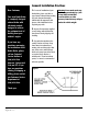
General Installation Practices Dear Customer, Your new Banks Brake is a uniquely designed exhaust brake with electronic controls, designed to achieve the optimum level of braking from your vehicle’s engine. If you have any questions concerning the installation of the Banks Brake, please call our Technical Service Hotline at (888) 839-2700 between 7:00 am and 5:00 pm (PT). If you have any questions relating to shipping or billing, please contact our Customer Service Department at (888) 839-5600. Thank you.
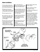
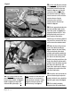
Brake Installation ground of the battery (if there is more than one battery, disconnect both). Using a reciprocating saw or hacksaw, make a straight cut through the pipe at the indicated location. 2. Remove the air-cleaner box 6. Locate the ball flange at the inlet assembly (including the black flex hose) from the passenger side of the vehicle. 3. Lift and support the vehicle. of the turbine outlet pipe.
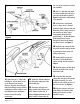
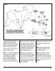
two 4-40 screws, washers and nylock nut assemblies. Figure 3 14. Drill a 1⁄8" pilot hole and mount the actuator control valve to the upper passenger side firewall as shown in Figure 4 using the #12 self-threading screw provided. 15. On the driver’s side firewall, there is a large, soft 31⁄2"-diameter grommet located under the cowl that allows the vehicle’s wiring harness to pass from the cab to the engine compartment.
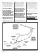
Figure 5 Figure 6 21. Locate the orange wire with dark blue stripe from pin 23 at connector A (black, right most connector), see Figure 6. For 94-95 vehicles, this wire will be located at pin 22 of the pcm connector. 22. Plug the connector on the end of the blue wire from the Banks Brake harness into the red t-tap installed in Step 21. 23. Plug the connectors in the green and black wires from the Banks Brake harness into the connectors on the black solenoid valve leads. 96986 v.3.
Figure 7 25. (‘94-97 only) Plug the connector on the end of the gray wire from the Banks Brake harness into the t-tap installed in Step 24. (‘98) Plug the connector on the end of the gray wire from the banks brake harness into the connector on the end of the extension harness. Plug the connector on the end of the extension harness into the t-tap installed in Step 24. 26. Find an appropriate location for the brake activation switch on the lower dash panel. See Figure 9 for suggested locations.
Figure 9 recommends mounting the CBC module in the location shown in Figure 8. Ensure that the mounting surface is clean and free of any oil, grease, or dirt. Clean and dry as required using a cloth and rubbing alcohol or similar solution. 31. Using a factory screw, attach the 33. Plug the 14-pin connector of the ring terminal on the end of the black wire from the 14-pin connector on the Banks Brake harness to the metal dash supports.
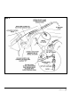
36. Find the OEM hose running 39. Use the remaining length of from the vacuum pump/check valve just foreword of the vehicle power steering pump. Disconnect the 90 degree elbow and install the brass T-fitting as shown in Figure 10. blue silicone hose to connect the vacuum supply to the actuator control valve and actuator. Run a length of hose from the brass 1⁄4" T-fitting up to the factory vacuum manifold on the firewall and across the cowl area to the previously installed actuator control valve. 37.
Figure 11 96986 v.3.
Exhaust Valve Spring Removal/Installation 43. Disconnect the battery negative Your Banks Brake is designed to provide the maximum retarding force possible from your engine. This will require the installation of heavy-duty exhaust valve springs designed to work with the increased backpressure created by the Banks Brake system. CAUTION: Exhaust valve spring replacement requires a thorough understanding of engine/valve train assembly and operation.
58. Carefully, release the replaced. For the two rear cylinders where clearance is limited, remove the plastic handle from the valve spring compressor and rotate the shaft with a wrench. compression on the spring and remove the spring from the tool. Functional Testing 57. Remove the valve spring and valve spring compressor tool from the valve stem. 59. Install a new exhaust valve spring into the tool and compress the spring using the same procedure outlined in Step 12. 60.
Figure 12 Figure 13 12 | 9 6 9 8 6 v.3.
Safety Caution: Your Banks Brake is NOT a substitute for the hydraulic brakes on your truck. The device will not correct or compensate for improperly maintained hydraulic brakes. Also please be aware that your Banks Brake is not designed to be used as a parking brake or to bring your vehicle to a complete stop. Your Banks Brake is a supplementary braking system designed to help you slow down or to assist you in maintaining a more constant speed when descending a grade.
1 2 3 4 5 6 7 8 9 10 Exhaust Brake Assembly Wire Harness Fuse, 15A Turbine Outlet Pipe Actuator Control Valve Valve Bracket Valve Filter Nylon Ties (15) Blue T-tap (2) Switch 14 | 9 6 9 8 6 v.3.0 11 12 13 14 15 16 17 18 19 Cover Plate 5⁄ 16" AN Washer (5) 7⁄ 16" SAE Washer (2) 7⁄ 16-14 x 2" Stainless Bolt (2) 8mm x 25mm Long Bolt (4) 8mm x 40mm Long Bolt (1) 4-40 Nylock Nut (2) #12 x 3⁄4" Long Sheet Metal Screw (2) 4-40 Screw x .
Banks Brake, General Assembly 96986 v.3.
Gale Banks Engineering 546 Duggan Avenue • Azusa, CA 91702 (626) 969-9600 • Fax (626) 334-1743 Product Information & Sales: (800) 438-7693 Customer Support: (888) 839-5600 Installation Support: (888) 839-2700 bankspower.com 16 | 9 6 9 8 6 v.3.