Muting Module Models MMD-TA-11B and MMD-TA-12B Instruction Manual Features • Compact, 67.5 mm DIN-mounted housing with plug-in terminal blocks. • For use with EZ-SCREEN® Output Signal Switching Device (OSSD) outputs or MINI-SCREEN®, MICROSCREEN®, MACHINE-GUARD®, or other safety devices with hard relay contact safety output(s) or +24V dc (PNP) outputs. • Monitors two or four inputs to automatically suspend the safety function of a safeguarding device.
Table of Contents Important ... read this before proceeding! In the United States, the functions that the Banner MMD-TA-11B and MMD-TA-12B Muting Modules are intended to perform are regulated by the Occupational Safety and Health Administration (OSHA). Outside of the United States, these functions are regulated by a variety of agencies, organizations, and governments.
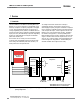
MMD-TA-11B / MMD-TA-12B Muting Module Overview Instruction Manual 1. Overview 1.1 Introduction The Banner MMD-TA-11B / MMD-TA-12B Muting Module (the Module) is an accessory component of a safeguarding system, which may incorporate such primary safeguards as safety light screens, safety interlocked gates/guards, or other presencesensing safeguarding devices (PSSDs).
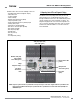
MMD-TA-11B / MMD-TA-12B Muting Module Overview Instruction Manual Individual features discussed in the following sections are: - Operating Status LEDs and Diagnostic Display - Auto/manual reset - Lockout conditions - Control reliability - Mutable Safety Stop Interface (MSSI) - Safety Stop Interface (SSI) - Output Signal Switching Device (OSSD) outputs - Auxiliary (AUX) output - External device monitoring (EDM) - Mute devices and mute inputs (M1−M4) - Mute enable input (ME) - Mute lamp output (ML) - Bac
MMD-TA-11B / MMD-TA-12B Muting Module Overview Instruction Manual 1.3 Automatic or Monitored Manual Reset Select The selectable Automatic or Monitored Manual Reset (X1−X2) provides flexibility for the user who has applications in which the operator is continually sensed, or in applications where the operator can pass through and become clear of the sensing field (see Section 3.1.4, “Pass-Through Hazards”) or other applications requiring a manual reset.
Overview 1.6 Muteable Safety Stop Interface (MSSI) The Muteable Safety Stop Interface (MSSI) input (S11−S12, S21−S22) is a specialized SSI that can be muted during the nonhazardous portion of the machine cycle. The Module requires redundant input signals from the external primary safeguard which is to be muted. These inputs typically are either two Banner solid-state safety outputs or two monitored forced-guided relay outputs from an appropriate safety device. See Section 2, Specifications, and Section 3.5.
MMD-TA-11B / MMD-TA-12B Muting Module Overview Instruction Manual 1.11 Mute Inputs (M1−M4) and Mute Devices The Muting Function To mute the primary safeguard appropriately, the design of a muting system must: 1. Identify the non-hazardous portion of the machine cycle, 2. Involve the selection of the proper muting devices, and 3. Include proper mounting and installation of those devices.
Overview 1.13 Mute Lamp Output (ML) Some applications require that a lamp (or other means) be used to indicate when the safety device (e.g., light screen) is muted; the module provides for this (X3−X4; see Caution below). This indication is selectable between a monitored or a non-monitored output signal (NPN sinking). The monitored output will prevent the initiation of a mute after an indicator failure is detected (current draw falls below 10 mA or goes above 360 mA).
MMD-TA-11B / MMD-TA-12B Muting Module Overview Instruction Manual 1.16 Override The Override function (X9−X10, X11−X12) allows the user to manually force the OSSD outputs ON for up to 30 seconds in a situation such as an object becoming “stuck” in the defined area of a safety light screen after the mute ends (e.g., a car body on a transfer line entering a work cell). The feature is intended to allow the user to “jog” the part out of the defined area.
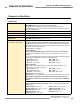
Components and Specifications MMD-TA-11B / MMD-TA-12B Muting Module Instruction Manual 2. Components and Specifications 2.1 Specifications System Power Requirements Model MMD-TA-11B: +24V dc ±15% @ 300 mA max (SELV/PELV) Model MMD-TA-12B: +24V dc ±15% @ 250 mA max (SELV/PELV) (not including draw of the MSSI power, AUX, ML, M1-M4 and OSSD connections). The external voltage supply must be capable of buffering brief mains interruptions of 20 ms, as specified in IEC/EN 60204-1.
MMD-TA-11B / MMD-TA-12B Muting Module Instruction Manual Components and Specifications 2.1 Specifications, continued Non-Safety Outputs Model MMD-TA-11B: Aux. output 31–32 is a parallel connection of two N.C. contacts from internal relays K1 and K2. Contact: AgNi, 5 µm gold-plated Low Current Rating: Caution: The 5 µm gold-plated contacts allow the switching of low current/low voltage.
Components and Specifications MMD-TA-11B / MMD-TA-12B Muting Module Instruction Manual 2.1 Specifications, continued Inputs The MSSI and the SSI can be interfaced with external devices that have either hard contact outputs or solid state sourcing outputs. When connecting the MSSI (S11–S12, S21–S22) or SSI (X5–X6, X7–X8) inputs to relay outputs or hard contacts, these contacts must be capable of switching 15–30V dc at 10–50 mA.
MMD-TA-11B / MMD-TA-12B Muting Module System Installation Instruction Manual 2.1 Specifications, continued Application Notes Mute Timing Sequences: see Appendix A Typical Muting Applications: see Appendix B Application Standards: see inside back cover 2.
System Installation MMD-TA-11B / MMD-TA-12B Muting Module Instruction Manual 3. System Installation 3.1 Appropriate Application The correct application of the MMD-TA-11B and -12B Muting Modules is dependent on the type of machine and the safeguards that are to be interfaced with the Module. The Module is generally interfaced with safeguards that may be used only on machinery that is capable of stopping motion immediately upon receiving a stop signal and at any point in its machine cycle.
MMD-TA-11B / MMD-TA-12B Muting Module System Installation Instruction Manual 3.1.1 Muting Application Design Following are typical applications where muting is used. See Appendix B for more detailed information. • Entry/Exit Applications. The muting devices are placed to allow the entry or exit of a pallet or cart of work materials to enter or exit a workstation without tripping the safety light screen, and without allowing the entrance of personnel into the hazardous area.
System Installation 3.1.4 Pass-Through Hazards A “pass-through hazard” is associated with applications where personnel may pass through a safeguard (at which point the hazard stops or is removed), and then may continue into the hazardous area. Subsequently, their presence is no longer detected, and the safeguard can not prevent the start or restart of the machine. The related danger is the unexpected start or restart of the machine while personnel are within the hazardous area.
MMD-TA-11B / MMD-TA-12B Muting Module System Installation Instruction Manual 3.3 Muting Module Configuration The Muting Module should be configured before initial checkout and use. Two banks of DIP switches are located under the front cover. To access the DIP switches, use a screwdriver to gently pry the cover loose from the Module housing. Because the Module has redundant microprocessors, two DIP switch banks (Bank A and Bank B) must be set identically.
MMD-TA-11B / MMD-TA-12B Muting Module System Installation Instruction Manual 3.4 Connection Terminals and Functions WARNING . . . Proper Electrical Hookup All electrical connections are made through removable terminals (see Figures 3-4a and 3-4b). Electrical hookup must be made by Qualified Personnel and must comply with NEC (National Electrical Code) and local standards.
MMD-TA-11B / MMD-TA-12B Muting Module System Installation Instruction Manual To remove a terminal block, insert a small screwdriver into the slot shown, and pry to loosen. When reinserting a terminal block, take care to slide the dovetail on the terminal block into the slot on the frame. Reset Routine The Muting Module requires a manual reset to clear a latch condition and resume operation following a stop command.
System Installation 3.5.2 Muting Devices The user is required by OSHA and ANSI to arrange, install, and operate the safety system so as to protect personnel and minimize the possibility of defeating the safeguard. Mute devices must meet a 3-second simultaneity requirement to activate muting; that is, devices in a pair must be activated within 3 seconds of one another.
MMD-TA-11B / MMD-TA-12B Muting Module System Installation Instruction Manual Muting Device Hookup The Module provides supply voltage, if required, and input connections for the muting devices. One or two pairs of muting devices (typically sensors or switches) must be used; these pairs are designated M1-M2 and M3-M4. The M1 and M3 inputs are PNP (sourcing). The M2 and M4 inputs are NPN (sinking). Also available are terminals to supply power (+24V dc) to the muting devices. +24V dc MMD-TA-..
MMD-TA-11B / MMD-TA-12B Muting Module System Installation Instruction Manual 3.5.3 Mute Lamp Output (ML) The Mute Lamp output provides for the visible indication that the safety device’s safeguarding function is muted. This indication must be readily observable. Failure of this indication should be detectable and prevent the safeguard from being muted, or the operation of the indicator should be verified at suitable intervals (see Section 1.13).
MMD-TA-11B / MMD-TA-12B Muting Module System Installation Instruction Manual 3.5.6 SSI and MSSI Interfacing The Safety Stop Interface (SSI) provides easy integration of safeguards. This interface consists of two input channels (A and B), which are compatible with Banner Engineering safety devices that have solid-state OSSD outputs or other devices with sourcing +24V dc outputs. SSI is also compatible with devices that have normally open hard contacts or relay outputs (voltagefree).
MMD-TA-11B / MMD-TA-12B Muting Module System Installation Instruction Manual Category 3 3.5.6.2 Generic SSI and MSSI Hookups To fully understand category requirements, refer to standard ISO 13849-1 (EN954-1). The following is general in nature and is intended to provide only basic guidance. Each guarding application has its unique set of requirements; it is the user’s responsibility to ensure that all local, state, and national laws, rules, codes, and regulations are satisfied.
MMD-TA-11B / MMD-TA-12B Muting Module System Installation Instruction Manual Category 4 To ensure a category 4 application, any device connected to the SSI and MSSI inputs must meet certain criteria. For example, a “type 4” safety light screen (curtain) that meets IEC 61496-1/-2 is a device that meets category 4 requirements. +24V dc 0V MMD-TA-..B A2 A1 MSSI or SSI In a category 4 application, a single fault must not cause the loss of the safety function.
MMD-TA-11B / MMD-TA-12B Muting Module System Installation Instruction Manual 3.5.6.3 SSI Emergency Stop Switch Device Hookup Emergency Stop Push Button Switches As shown in Figures 3-16, 3-17 and 3-18, the E-stop switch must provide one or two contacts for safety which are closed when the switch is armed.
MMD-TA-11B / MMD-TA-12B Muting Module System Installation Instruction Manual Category 3 A dual-channel hookup switching +24V dc is typically a category 3 application, because a single failure does not result in a loss of safety. Loss of the switching action in one channel is detected by the actuation of the E-stop button, the opening of the second channel, and the monitoring function of the SSI inputs. However, a short circuit between input channels or safety outputs may not be detected.
System Installation 3.5.6.4 SSI/MSSI Interlocked Guard or Gate Hookup The SSI (or MSSI) may be used to monitor electrically interlocked safety guards or gates. Safety Circuit Integrity Levels Requirements vary widely for the level of control reliability or safety category per ISO 13849-1 (EN954-1) in the application of interlocked guards.
MMD-TA-11B / MMD-TA-12B Muting Module System Installation Instruction Manual The systems in either scenario do not inherently comply with the safety standard requirements of detecting single faults and preventing the next cycle. In multiple-guard systems using series-connected safety switches, it is important to periodically check the functional integrity of each interlocked guard individually.
MMD-TA-11B / MMD-TA-12B Muting Module System Installation Instruction Manual Category 3 +24V dc A dual-channel hookup switching +24V dc is typically a category 3 application, because a single failure does not result in a loss of safety. Loss of the switching action in one channel is detected by the actuation of opening and closing the guard, allowing the monitoring function of the MSSI or SSI inputs to detect the discrepancy between the channels.
MMD-TA-11B / MMD-TA-12B Muting Module System Installation Instruction Manual information. This application is widely used in a variety of situations, including manufacturing cells, robotic cells, palletizers, and de-stackers. One of the many requirements of this muting application is that it must not be possible for personnel to walk in front of, behind, or next to the muted object (e.g., the carrier basket) without being detected and stopping the hazardous motion. 3.5.6.
System Installation 3.6 Machine Interface – Initial Hookup and Checkout Model MMD-TA-11B provides two normally open safety relay output contacts (13−14 and 23−24) to hook up external MPCE1 and MPCE2 (see Figures 3-27 and 3-28). Model MMD-TA-12B provides two PNP solid-state safety outputs, OSSD1 and OSSD2 (Y5−Y6 and Y7−Y8) see Figures 3-24, 3-25, and 3-26. For monitoring external devices (both models), normally closed contacts of these devices must be hooked up to EDM #1 (Y1−Y2) and EDM #2 (Y3–Y4).
MMD-TA-11B / MMD-TA-12B Muting Module Instruction Manual If the Muting function is not used, proceed to Section 3.7. During the initial checkout procedure of the Muting feature, if possible, verify that the power has been removed or is otherwise not available to the machine actuators responsible for hazardous motion. At all times ensure that personnel are not exposed to any hazard. 7. Mute the System by blocking (or activating) both mute devices (typically M1 and M2) simultaneously (within 3 seconds). 8.
MMD-TA-11B / MMD-TA-12B Muting Module System Installation Instruction Manual 3.7.1 Mute Enable Hookup 3.7.2 External Device Monitoring (EDM) Hookup The Module provides a Mute Enable input (“ME,” X13−X14) for the connection of a potential free contact (see Section 1.12). Mute Enable gives the user the ability to “frame” or create a “window of opportunity” when a mute can occur. When configured, the Mute Enable input is a contact that must be closed before the safeguard can be muted.
MMD-TA-11B / MMD-TA-12B Muting Module Instruction Manual 3.7.3 OSSD Output Connections Both the output signal switching device (OSSD) outputs must be connected to the machine control such that the machine’s safety related control system interrupts the circuit or power to the machine primary control element(s) (MPCE), resulting in a nonhazardous condition. This applies equally to the safety relays of the model MMD-TA-11B and the solid-state output of the model MMD-TA-12B.
System Installation Dual-Channel Control MMD-TA-11B / MMD-TA-12B Muting Module Instruction Manual Methods to exclude the possibility of these failures include, but are not limited to: Dual-channel (or two-channel) control has the ability to electrically extend the safe switching point beyond the FSD contacts. With proper monitoring (i.e., EDM), this method of interfacing is capable of detecting certain failures in the control wiring between the safety stop circuit and the MPCEs.
MMD-TA-11B / MMD-TA-12B Muting Module System Installation Instruction Manual +24V dc WARNING . . . Use of Transient Suppressors 0V dc A1 MMD-TA-12B A2 EDM1 Y1 Y2 EDM2 Y3 Y4 + OSSD1 OSSD2 NOTE: Do not exceed OSSD maximum load capacitance specifications. Y5 + 0V Y6 0V Y7 Y8 FSD1 Transient suppressors are recommended. They MUST be installed across the coils of the machine control elements.
MMD-TA-11B / MMD-TA-12B Muting Module System Installation Instruction Manual 0V dc +24V dc A1 MMD-TA-12B A2 Y1 EDM1 Y2 Y3 EDM2 Y4 + OSSD1 OSSD2 Y5 + 0V Y6 0V Y7 Y8 IM-T-9A S3 S1 K2 +24V dc WARNING . . . OSSD Interfacing To ensure proper operation, the Muting Module output parameters and machine input parameters must be considered when interfacing the Muting Module solid-state OSSD outputs to the machine inputs.
MMD-TA-11B / MMD-TA-12B Muting Module System Installation Instruction Manual 0V dc +24V dc A1 MMD-TA-12B A2 EDM1 Y1 Y3 Y4 + OSSD1 OSSD2 Y5 + 0V Y6 0V Y7 Use of Transient Suppressors Transient suppressors are recommended. They MUST be installed across the coils of the machine control elements. NEVER install suppressors directly across the outputs of the Module! It is possible for suppressors to fail as a short circuit.
MMD-TA-11B / MMD-TA-12B Muting Module System Installation Instruction Manual +24V dc 0V dc A1 MMD-TA-11B +24V dc A2 0V dc A1 MMD-TA-11B A2 Y1 Y1 EDM1 EDM1 Y2 Y2 Y3 Y3 EDM2 EDM2 Y4 L1 Machine Control Circuits 13 K1A K2A K1B K2B L2 14 23 24 31 32 K1C Y4 MPCE1 MPCE2 K2C Figure 3-27. Generic machine interface hookup, model MMD-TA-11B: MPCE with 2-channel EDM WARNING . . . Use of Transient Suppressors Transient suppressors are recommended.
MMD-TA-11B / MMD-TA-12B Muting Module Operating Instructions Instruction Manual 4. Operating Instructions 4.1 Security Protocol 4.3 Normal Operation The Module must be mounted inside a lockable enclosure or cabinet rated IP54 or better, both to protect the Module from environmental conditions and in order to prevent access by unauthorized personnel, if required by applicable standards. During normal operation, the Module’s three status indicators (red, green and yellow) are as shown in Figure 4-1.
MMD-TA-11B / MMD-TA-12B Muting Module Troubleshooting and Maintenance Instruction Manual 5. Troubleshooting and Maintenance 5.1 Troubleshooting Lockout Conditions A lockout condition causes the OSSD outputs to turn OFF, sending a stop signal to the guarded machine. A lockout condition is indicated by the Red status indicator flashing and an error code appearing in the Diagnostic Display.
MMD-TA-11B / MMD-TA-12B Muting Module Instruction Manual Status Error Code Condition / Error Type / Action — (Solid) System OK — (Flashing) Mute Cycle 31 OSSD Output Error - One OSSD is shorted to power/ground - OSSDs are shorted together 32 Reset Input Error - Reset input shorted/closed 33 Module Error - Excessive EMI/RFI noise - Internal failure, replace Module 34 MSSI Error* - One or both channels shorted to power or ground - Input channels shorted together - One channel did not open - Fa
Periodic Checkout Procedures MMD-TA-11B / MMD-TA-12B Muting Module Instruction Manual 6. Periodic Checkout Procedures Study each procedure from beginning to end before you start to make sure that you understand each step. Refer all questions to the Banner Applications Engineering Department at the address or numbers listed on the front cover of this manual. Checkouts must be performed as detailed in Section 6.1 below and results should be recorded and kept in the appropriate place (e.g.
MMD-TA-11B / MMD-TA-12B Muting Module Instruction Manual 6. Apply power to the Module. Ensure that power to the guarded machine is OFF. Verify that the external safety systems are providing a Green/Go signal to the MSSI and SSI inputs, and that the Green MSSI and SSI indicators (two pairs of LEDs located near each terminal) are ON. When configured for Manual Reset, the Yellow status indicator will be flashing. Perform a manual reset (close the Reset switch for 1/4 to 2 seconds, then open the switch).
Periodic Checkout Procedures 6.3 Daily Checkout Perform this checkout procedure at every shift change, powerup and machine set-up change. During continuous machine run periods, this checkout must be performed at intervals not to exceed 24 hours. A Designated Person or Qualified Person (as defined in Section 1.18) must perform the procedure; checkout results should be recorded and kept on or near the guarded machine, per OSHA 1910.217(e)(1). 1.
MMD-TA-11B / MMD-TA-12B Muting Module Appendix A Instruction Manual Appendix A. Mute Timing Sequences Muting Sequence with Two Muting Devices (For example, “X”-pattern Entry/Exit System, see Figure B-1) Power System Reset DIP Switch Configuration*: MSSI Auto or Manual Reset . . . SW1 = OFF (Manual) AUX Outputs MMD-TA-11B SSI Auto or Manual Reset . . . . SW2 = OFF (Manual) or ON (Auto) OSSD Outputs One-Way Muting . . . . . . . . . . . . SW3 = OFF (1-way) EDM Two-/One-Channel EDM . . . . . .
MMD-TA-11B / MMD-TA-12B Muting Module Appendix B Instruction Manual Appendix B. Typical Muting Applications Entry/Exit Applications The muting devices must be placed to ensure that the points that trigger the mute’s start and end are very close to the safety light screen’s sensing field. This prevents personnel from following, or being pushed by, the object into the hazardous area without interrupting the safety light screen before the mute window opens or at the time the mute window closes.
MMD-TA-11B / MMD-TA-12B Muting Module Appendix B Instruction Manual A ≥ (speed of line ft/sec) x 0.1 sec. B ≈ 3" or position must hinder personnel following muted object C ≤ Length of carrier basket Hard Guarding M1 Carrier Basket M3 R – Trapping hazards must be avoided and clearance requirements complied with. – Switch actuators can not be so long that they allow a single person to initiate a muted condition.
MMD-TA-11B / MMD-TA-12B Muting Module Appendix B Instruction Manual Home or Station Applications The muting devices must be placed to ensure that the safety light screen is muted only when the hazard does not exist or is in another area so that personnel are not exposed. The muting devices must be placed so that if a hazard arises, or the hazard enters the safeguarded area, the mute will immediately end and the safeguard will be active once again.
MMD-TA-11B / MMD-TA-12B Muting Module Appendix B Instruction Manual Robot Load/Unload Station Application This “station” muting application uses two independent safety light screen circuits, each with its own muting circuit and muting devices (e.g. polarized-retroreflective photoelectrics). The application also includes run bars with two-hand control, auxiliary controls, and E-Stop.
MMD-TA-11B / MMD-TA-12B Muting Module Appendix B Instruction Manual Turret Table Application A “Turret Table” application is similar to the Robot Load/Unload Station muting application, except that any movement of the table ends the mute. To accomplish this, small retroreflective targets (or tape) are positioned so that they will initiate the mute (the sensors must be set to “Light Operate”) only after the table has finished indexing.
MMD-TA-11B / MMD-TA-12B Muting Module Instruction Manual Power Press Applications Muting is allowed on power presses only during the nonhazardous portion of the cycle (e.g. the upstroke), per OSHA1910.217, ANSI B11.1, B11.2, and B11.3. The mute permits the insertion or removal of material into the press that would otherwise block the sensing field of the safety light screen, causing the press to stop.
Glossary of Terms MMD-TA-11B / MMD-TA-12B Muting Module Instruction Manual Glossary of Terms ANSI (American National Standards Institute): the American National Standards Institute, an association of industry representatives that develops technical standards (including safety standards). These standards comprise a consensus from a variety of industries on good practice and design. ANSI standards relevant to application of safety products include the ANSI B11 Series, and ANSI/RIA R15.06.
MMD-TA-11B / MMD-TA-12B Muting Module Instruction Manual Glossary of Terms Hazard Point: the closest reachable point of the hazardous area. OSSD: Output Signal Switching Device. The safety outputs that are used to initiate a stop signal. Internal Lockout: a Lockout condition that is due to an internal safety system problem. Generally, indicated by the red Status indicator LED (only) flashing. Requires the attention of a Qualified Person.
Glossary of Terms MMD-TA-11B / MMD-TA-12B Muting Module Instruction Manual Test Piece: an opaque object of sufficient size used to block a light beam to test the operation of a safety light screen system. Trip Condition: the response of the safety outputs (e.g., OSSDs) of a safety light screen system when an object equal to or greater than the diameter of the specified test piece enters the defined area. In a Trip condition, the OSSDs simultaneously deenergize.
MMD-TA-11B / MMD-TA-12B Muting Module Instruction Manual Notes Banner Engineering Corp. • Minneapolis, U.S.A. www.bannerengineering.com • Tel: 763.544.3164 P/N 116390 rev.
Notes MMD-TA-11B / MMD-TA-12B Muting Module Instruction Manual Banner Engineering Corp. • Minneapolis, U.S.A. 56 P/N 116390 rev. C www.bannerengineering.com • Tel: 763.544.
The list of standards below is included as a convenience for users of this Banner product. Inclusion of these standards does not imply that the product complies specifically with any standard, other than those listed in the Specifications section of this manual. SOURCES OSHA Documents Superintendent of Documents Government Printing Office P.O. Box 371954 Pittsburgh, PA 15250-7954 Tel: (202) 512-1800 http://www.osha.
WARRANTY: Banner Engineering Corp. warrants its products to be free from defects for one year. Banner Engineering Corp. will repair or replace, free of charge, any product of its manufacture found to be defective at the time it is returned to the factory during the warranty period. This warranty does not cover damage or liability for the improper application of Banner products. This warranty is in lieu of any other warranty either expressed or implied. P/N 116390 rev. C Banner Engineering Corp.