
Manual

8 P/N 116390 rev. C
Banner Engineering Corp. • Minneapolis, U.S.A.
www.bannerengineering.com • Tel: 763.544.3164
MMD-TA-11B / MMD-TA-12B Muting Module
Instruction Manual
Components and Specifications
2. Components and Specifications
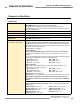
2.1 Specifications
System Power Requirements Model MMD-TA-11B: +24V dc ±15% @ 300 mA max (SELV/PELV)
Model MMD-TA-12B: +24V dc ±15% @ 250 mA max (SELV/PELV)
(not including draw of the MSSI power, AUX, ML, M1-M4 and OSSD connections).
The external voltage supply must be capable of buffering brief mains interruptions of 20 ms, as
specified in IEC/EN 60204-1.
Overvoltage Category III (IEC 60664-1)
Pollution Degree 2
Supply Protection Circuitry All inputs and outputs are protected from short circuit to +24V dc or dc common.
Response Time
(MSSI and SSI)
Model MMD-TA-11B: (relay output) 20 ms max.
Model MMD-TA-12B: (solid-state output) 10 ms max.
Safety Outputs
(see Warning on pages 32-34)
Model MMD-TA-11B:
2 normally open contact output channels and 1 normally closed auxiliary contact output
channel: Each normally open output channel is a series connection of contacts from two forced-
guided (positive-guided) relays, K1-K2. The normally closed AUX contact (non-safety) 31-32 is a
parallel connection of contacts from K1-K2.
Contacts: AgNi, 5 μm gold-plated
Low Current Rating:
Caution: The 5 μm gold-plated contacts allow the switching of low current/low voltage.
In these low-power applications, multiple contacts can also be switched in series (e.g., “dry
switching”).
To preserve the gold plating on the contacts and also guarantee reliable switching, the following
values should be kept within the min. and max. ranges shown below:
Min. voltage: 1V ac/dc
Max. voltage: 60V
Min. current: 5 mA ac/dc
Max. current: 300 mA
Min. power: 5 mW (5 mVA)
Max. power: 7 W (7 VA)
High Current Rating:
If higher loads must be switched through one or more of the contacts, the minimum and
maximum values of the contact(s) changes to:
Min. voltage: 15V ac/dc
Max. voltage: 120V ac/dc
Min. current:
30 mA ac/dc Max. current: 6 A
Min. power:
0.45 W (0.45 VA) Max. power: 160 W (720 VA)
Mechanical life: 50,000,000 operations
Electrical life: 120,000 operations (typical, @ 144 W [1,380 VA] switched power, resistive load)
NOTE: Transient suppression is recommended when switching inductive loads. Install
suppressors across load. Never install suppressors across output contacts (see Warning,
page 35).
Model MMD-TA-12B:
2 diverse-redundant solid-state safety outputs: 24V dc, 0.5 A sourcing OSSD (output signal
switching device).
ON-State voltage: ≥ Vin–1.5V dc Cable resistance: 10 ohms maximum
OFF-State voltage: 1.2V dc max. (0–1.2V dc) OSSD test pulse width: < 100 µs
Max. load capacitance: 1.0 µF OSSD test pulse period: > 100 ms
Max. load inductance: 10 H Switching current: 0–0.5 A
Leakage current: 0.50 mA maximum
Specifications continued on page 9.