
Manual

2 P/N 116390 rev. C
Banner Engineering Corp. • Minneapolis, U.S.A.
www.bannerengineering.com • Tel: 763.544.3164
MMD-TA-11B / MMD-TA-12B Muting Module
Instruction Manual
Overview
Individual features discussed in the following sections are:
- Operating Status LEDs and Diagnostic Display
- Auto/manual reset
- Lockout conditions
- Control reliability
- Mutable Safety Stop Interface (MSSI)
- Safety Stop Interface (SSI)
- Output Signal Switching Device (OSSD) outputs
- Auxiliary (AUX) output
- External device monitoring (EDM)
- Mute devices and mute inputs (M1−M4)
- Mute enable input (ME)
- Mute lamp output (ML)
- Backdoor timer
- Mute on power-up
- Override
- One-way/two-way muting
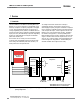
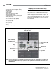
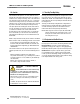
Figure 1-2. Muting Module features
1.2 Operating Status LEDs and Diagnostic Display
The Module has three Operating Status LEDs (one each red,
yellow and green), plus a 2-digit Diagnostic Display, visible
through a window in the front cover. The individual LEDs provide
constant, ongoing system status information at a glance. The
Diagnostic Display provides error codes that correspond to the
cause of a fault or configuration error which results in a lockout,
and other more detailed conditions. See Sections 4 and 5 for
further information.
Muteable Safety Stop
Input(s) (MSSI)
Active LEDs (green)
Safety Stop Inputs (SSI)
Active LEDs (green)
Reset Input
(green)
2-Digit
Diagnostic Display
NOTE: A green or yellow indicator is provided for each input to verify an active state. A green indicator is provided for the
Reset Input and for MSSI and SSI inputs. A yellow indicator is provided for each of the mute device (M1–M4) and
OVERRIDE inputs.
Red, Green,
Yellow Status
LEDs
Override Active LEDs
(yellow)
Muting Devices
Status LEDs (yellow)