
Manual

P/N 116390 rev. C 3
Banner Engineering Corp. • Minneapolis, U.S.A.
www.bannerengineering.com • Tel: 763.544.3164
MMD-TA-11B / MMD-TA-12B Muting Module
Instruction Manual
Overview
1.3 Automatic or Monitored Manual Reset Select
The selectable Automatic or Monitored Manual Reset (X1−X2)
provides flexibility for the user who has applications in which
the operator is continually sensed, or in applications where the
operator can pass through and become clear of the sensing
field (see Section 3.1.4, “Pass-Through Hazards”) or other
applications requiring a manual reset.
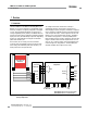
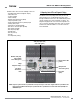
The configuration is selected via two banks of DIP switches
located under the Module’s front cover (see Figures 1-2 and
3-2).
Monitored Manual Reset
Manual Reset is typically used in situations where the individual
can pass through a sensing field and become clear of a
safeguarding device, such that the device can no longer prevent
hazardous motion (e.g., perimeter guarding). The Module
“monitors” the input for two transitions: from open-to-closed, and
from closed-to-open within a certain time period. This prevents
the reset button from being tied down or failing in a closed
condition, and causing an unintended or automatic reset.
Upon power-up, when the Module has been configured for
manual reset, for the OSSD outputs to turn ON, both the MSSI
and the SSI must be active (closed) and a monitored manual
reset must be accomplished. The reset is accomplished by
closing the Reset input for a minimum of 1/4 second, but not
longer than 2 seconds and then re-opening the input. The OSSD
outputs will turn ON once the open-closed-open action occurs.
In this configuration, the Module must be manually reset after
power-up, lockouts, and after the cycling of either the MSSI (not
muted) or the SSI. The location for the manual reset device
(e.g., a normally open key switch) must comply with the warning
in Section 3.5.1 and refer to that section for further information
on key resets.
Automatic Reset
Upon power-up, when the Module is configured for automatic
reset, the OSSD outputs will automatically turn ON once power
is applied, the self-test is accomplished, and the MSSI and the
SSI are active (closed). The OSSD outputs will also turn ON
after either interface is de-activated and then re-activated. In
either case, no external input or reset is required.
Automatic reset is typically used in situations where the
individual is continually sensed by the defined area or in
situations where supplemental safeguards prevent the initiation
of hazardous motion while an individual is within the safeguarded
space (e.g., point-of-operation guarding).
In either case, a manual reset must be performed to recover
from a lockout condition.
In Automatic Reset mode, input X1−X2 stays open.
1.4 Lockout Conditions
A lockout condition of the Module will cause both OSSD outputs
to go OFF. A lockout condition is indicated by a flashing Red
status indicator and an error number displayed on the Diagnostic
Display.
A description of possible lockouts, their causes, troubleshooting
hints, and a Manual Reset routine are listed in Section 5.
1.5 Control Reliability: Redundancy and Self-Checking
Redundancy requires that Module circuit components be
“backed up” to the extent that, if the failure of a single
component will prevent effective machine stopping action when
needed, that component must have a redundant counterpart
which will perform the same function. The microprocessor-
controlled Muting Module is designed with diverse redundancy.
Diverse-redundant components are of different designs, and
microprocessor programs used by them run from different
instruction sets.
Redundancy must be maintained for as long as the Muting
Module is in operation. Since a redundant system is no longer
redundant once a component has failed, the Module is designed
to be continuously self-checking. A component failure detected
by or within the self-checking system causes a “stop” signal
to be sent to the guarded machine and puts the Module into a
lockout condition.
Recovery from this type of lockout condition requires
replacement of the failed component (to restore redundancy) and
the appropriate reset procedure (see Section 3.5.1). Possible
causes are listed in Section 5. The Diagnostic Display is used to
diagnose causes of a lockout condition (Section 5).