
Manual

4 P/N 116390 rev. C
Banner Engineering Corp. • Minneapolis, U.S.A.
www.bannerengineering.com • Tel: 763.544.3164
MMD-TA-11B / MMD-TA-12B Muting Module
Instruction Manual
Overview
1.6 Muteable Safety Stop Interface (MSSI)
The Muteable Safety Stop Interface (MSSI) input (S11−S12,
S21−S22) is a specialized SSI that can be muted during the non-
hazardous portion of the machine cycle.
The Module requires redundant input signals from the external
primary safeguard which is to be muted. These inputs typically
are either two Banner solid-state safety outputs or two monitored
forced-guided relay outputs from an appropriate safety device.
See Section 2, Specifications, and Section 3.5.6 for complete
information.
1.9 Auxiliary Output (Aux)
The Auxiliary (Aux) monitoring PNP (Z3−Z4) output on the
MMD-TA-12B and the parallel N.C. contact output on the -11B
are intended for non-safety related purposes. The status of
this auxiliary output is indicated by the green Status LED. See
Section 3.5.4 for more information.
1.10 External Device Monitoring (EDM)
Two inputs are provided (see Figures 3-24 to 3-28) for monitoring
the state of external devices, such as MPCEs. These terminals
are labeled “EDM1” (Y1−Y2) and “EDM2” (Y3−Y4). The Module’s
EDM inputs can be configured in three ways: one-channel, two-
channel, or no monitoring (see Figure 3-2 for DIP switch settings
and Section 3.7.2 for external hookup). One- and two-channel
EDM are used when the OSSD outputs directly control the de-
energizing of the MPCEs or external devices.
• One-Channel Monitoring: a series connection of closed
monitor contacts that are forced-guided (mechanically linked)
from each device controlled by the Muting Module. The monitor
contacts must be closed before the Module can be reset (either
Manual or Automatic). After a reset is executed and the safety
outputs (OSSDs) are closed, the status of the monitor contacts
is no longer monitored. However, the monitor contacts must be
closed within 200 milliseconds of the OSSD outputs going from
ON to OFF.
• Two-Channel Monitoring: an independent connection of
closed monitor contacts that are forced-guided (mechanically
linked) from each device controlled by the Muting Module. Both
EDM inputs must be closed before the Module can be reset and
the OSSDs can turn ON. While the OSSDs are ON, the inputs
may change state (either both open, or both closed). If the
inputs remain in opposite states for more than 200 milliseconds,
a lockout will occur. Additionally, both inputs must be closed
200 milliseconds after the OSSD outputs go OFF, or a lockout
will occur.
•
No Monitoring: If no monitoring is desired, the 1-ch/2-ch
selection switches must be configured for two-channel EDM,
and Y1 must be jumpered to Y3. If the Module is set for No
Monitoring, the user must ensure that any single failure of the
external devices does not result in a hazardous condition and
a successive machine cycle will be prevented (see Section 1.5,
Control Reliability).
WARNING . . . Emergency Stop
Functions
Do not connect any Emergency Stop devices
to the MSSI Input; do not mute or bypass any Emergency
Stop device. ANSI NFPA79 and IEC/EN 60204-1 require
that the Emergency Stop function remain active at all times.
Muting or bypassing the safety outputs will render the
Emergency Stop function ineffective.
1.7 Safety (Protective) Stop Interface (SSI)
The Module has a provision for an additional Safety (Protective)
Stop Interface (X5−X6, X7−X8) to connect an optional device,
such as a supplemental safeguard, E-stop button, or safety
switch(es), to issue a stop command. This dual-channel interface
is similar to the MSSI, but is always functional, even when
the primary safety device is being muted. See Sections 2,
Specifications, and 3.5.6 for complete information.
1.8 OSSD Outputs
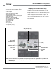
Model MMD-TA-12B has two solid-state safety outputs (Y5−Y6,
Y7−Y8); and model MMD-TA-11B has two normally open hard-
contact safety outputs (13−14, 23−24), labeled “OSSD1” and
“OSSD2” (see Figure 1-1). The solid-state safety outputs are
actively monitored to detect short circuits to the supply voltage,
to each other, and to other sources of electrical energy. If a
failure is detected, the outputs will switch to an OFF-state. For
circuits requiring the highest level of safety and reliability, either
OSSD must be capable of stopping the motion of the guarded
machine in an emergency.
During the muted portion of the machine cycle, the MSSI inputs
will be ignored and OSSD1 and OSSD2 will remain ON. During
other portions (not muted) of the cycle, if the MSSI either open
or go OFF, OSSD1 and OSSD2 will go OFF.
In any case, if the SSI interface opens, OSSD1 and OSSD2 will
go OFF. See Appendix A for timing diagrams.