
Manual

P/N 116390 rev. C 5
Banner Engineering Corp. • Minneapolis, U.S.A.
www.bannerengineering.com • Tel: 763.544.3164
MMD-TA-11B / MMD-TA-12B Muting Module
Instruction Manual
Overview
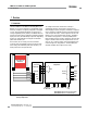
1.11 Mute Inputs (M1−M4) and Mute Devices
The Muting Function
To mute the primary safeguard appropriately, the design of a
muting system must:
1. Identify the non-hazardous portion of the machine cycle,
2. Involve the selection of the proper muting devices, and
3. Include proper mounting and installation of those devices.
The Module can monitor and respond to redundant signals that
initiate the mute (M1: Z11–Z21; M2: Z12–Z22; M3: Z13–Z23;
M4: Z14–Z24). The mute then suspends the safeguarding
function by ignoring the state of the MSSI. This allows a person
to interrupt the defined area to load and/or unload parts or
an object to pass through the defined area of a safety light
screen, without generating a stop command. (This should not be
confused with blanking, which disables one or more beams in a
safety light screen, resulting in larger resolution.) See Appendix
A for example mute timing sequences.
The mute may be triggered by a variety of external devices. This
feature provides a variety of options (see Sections 3.5.2 − 3.5.3)
to tailor the System to the requirements of a specific application.
A pair of muting devices must be triggered simultaneously (within
3 seconds of one another). This reduces the chance of common
mode failures or defeat.
WARNING . . . Muting Limitations
Muting is allowed only during the non-
hazardous portion of the machine cycle.
A muting application must be designed so that no single
component failure can prevent the stop command or allow
subsequent machine cycles until the failure is corrected
(per OSHA 1910.217(c)(3)(iii)(d), and ANSI B11.19).
WARNING . . . Mute Inputs Must Be
Redundant
It is not acceptable to use a single switch,
device, or relay with two N.O. contacts for the mute
inputs. This single device, with multiple outputs, may fail so
that the System is muted at an inappropriate time. This may
result in a hazardous situation.
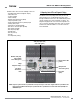
Mute Devices
The beginning and end of a mute cycle must be triggered by
outputs from either pair of muting devices, depending on the
application. The mute device pairs both must have normally
open contacts, or have one device with a PNP output and one
device with an NPN output, both of which fulfill the “muting
device requirements” in Sections 2 and 3.5.2. These contacts
must close (conduct) when the switch is actuated to initiate the
mute, and must open (non-conducting) when the switch is not
actuated and in a power-OFF condition.
The Module monitors the mute devices to verify that their outputs
turn ON within 3 seconds of each other. If the inputs do not meet
this simultaneity requirement, a mute condition can not occur.
Several types and combinations of mute devices can be used,
including, but not limited to: limit switches, photoelectric sensors,
positive-driven safety switches, inductive proximity sensors, and
“whisker” switches. (See Muting Device Requirements, Section
3.5.2.)
1.12 Mute Enable (ME)
The Mute Enable input (X13−X14) is a non-safety-rated input.
When the input is closed (terminals X13−X14 jumpered), the
Module will allow a mute condition to occur; opening this input
while the System is muted will have no effect. The Module
is factory-supplied with a jumper installed between terminals
X13−X14. To use the Mute Enable function, remove the jumper.
Typical uses for Mute Enable include:
• To allow the machine control logic to create a “window” for
muting to begin;
• To inhibit muting from occurring; or
• To reduce the chance of unauthorized or unintended
bypassing or defeat of the safety system.
Simultaneity Timer Reset Function
The Mute Enable input can also be used to reset the simultaneity
timer of the mute inputs. If one input is active for longer than
three seconds before the second input becomes active, the
simultaneity timer will prevent a mute cycle from occurring. This
could be due to a normal stoppage of an assembly line that may
result in blocking one mute device and the simultaneity time
running out.
If the ME input is cycled (closed-open-closed) while one mute
input is active, the simultaneity timer is reset, and if the second
mute input becomes active within three seconds, a normal mute
cycle begins. The timing requirement for the closed-open-closed
is similar to the manual reset function. Initially, the input needs
to be active (closed) for longer than 1/4 second, then open for
longer than 1/4 second, but not longer than 2 seconds, and then
must reclose to reset the simultaneity timer. The function can
reset the timer only once per mute cycle (i.e., all mute inputs
M1−M4 must open before another reset can occur).