HM- GY5202AC CR/BK 52-INCH DEROCATE CEILING FAN USE AND CARE GUIDE Ceiling fan
Safety Information 1. To reduce the risk of electric shock, the electricity has been turned off at the circuit breaker or fuse box before begin. 2. All wiring must be in accordance with the National Electrical Code NASI/NEPA 70-1999 and local electrical codes.Electrical installation should be performed by a qualified licensed electrician. 3. The outlet box and support structure must be securely mounted and capable of reliably supporting 35lbs. (15.9kg).
WARNING To reduce the risk of personal injury, do not bend the blade brackets (also referred to as flanges) during assembly or after installation. Do not insert objects in the path of the blades . Remove the rubber motor stops on the bottom of the fan before installing the blades or testing the motor. To reduce the risk of fire or electric shock, do not use this fan with any solid-state speed control device. To avoid possible electric shock, turn the electricity off at the main fuse box before wiring.
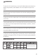
The above data are for reference only, Actually the motor speed of each ceiling fan is a little different. Any products, Subject to actual products as standard. These are approximate measures.They do not include NOTE the amps and wattage used by the light kit. Specifications & measurements shown are subject to± 5% variations.
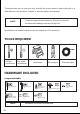
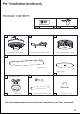
Pre-Installation(continued) PACKAGE CONTENTS R-T A B Fan-Motor assembly ×1PCS R-R remote control(transmitter) remote control(receiver) C Light kit fitter assembly ×1PCS Arm(with per- installed screws) ×5PCS D Blade X 5PCS Glass ×1PCS J E Slide - on mounting bracket (inside canopy) X 1PCS G 4.92 inch Ball/downrod assembly X 1PCS F Canopy X 1PCS H 9.84 inch Ball/downrod assembly X 1PCS I Coupling cover X 1PCS Pls check whether above accessories are completed or not?Yes, and install.
Installation of the hanging bracket (suspension part)(page-1) Mounting screws ×4 Expansion bolts ×2 WOODEN CEIING For wooden ceiling, use wood screw to drill on the wooden Mounting Bracket Washers beam or the "junction box" to fix the hanging bracket(selection is made according to actual Self tapping screw requirements of the customers) STEP 1 A-WOODEN CEILING SWITCH OFF THE ELECTRICAL MAINS AT THE CIRCUIT BREAKER FUSE BOX.
Installation of the hanging bracket (suspension part)(page-2) CÖNCRETE CEILING Mounting For concrete ceiling, use the percussion Bracket bit with diameter 8mm to drill holes according to the length of expansion Expansion Bolts Flat Washers screws. Then use the attached expansion screws to fix the hanging bracket onto Flat Washers the ceiling (selection is made according to Nuls actual requirements of the customers).
Electrical Outlet Box WARNING : Contact a qualified electrician to replace the outlet box if it is not suitable for ceiling cans □ If there is an existing outlet box,ensure it is clearly marked “Suitable for Fan Support”. if not, it must be replaced with an approve one. □ Secure the outlet box (or make sure the existing box is secured) directly to the building structure. Use appropriate fasteners and building materials.wood joist and outlet box must be able to support a minimum of 50 pounds.
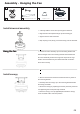
Assembly - Hanging the Fan E Slide - on mounting bracket (inside canopy) X 1PCS G F Canopy X 1PCS H A 4.92 inch Ball/downrod assembly X 1PCS 9.84 inch Ball/downrod assembly X 1PCS I Coupling cover x 1PCS Fan-Motor assembly ×1PCS Install downrod assembly □ Carefuly feed the molor wires up though the downrod □ Align the holes and replace hanger pin and locking pin. □ Tighten the two colar setscrews. □ Slip coupling cover,canopy coverand canopy onto the downrod.
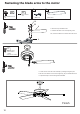
Fastening the blade arms to the motor D B DD Blade attachment screw ×16 EE Paper Washers ×16 Arm×5 Blade X 5PCS DD EE B □ Remove the pre installed screws □ Install the fan blade on the corresponding screw hole, and then install and fix it with the removed screws. D FF blade arm screw and lock washer ×10PCS (unscrew form motor) □ Fasten the arm to the fan-motor assembly by inserting the aligment post int the slot on the bottom of the motor and tightening the pre-installed armscews.
Assembly-Attaching the Lights C Light kit fitter assembly ×1 Motor kit Light kit White White Blue Blue □ Insert the “white” line in the switching box of the motor into the “white” line of the light and tie insulated rubber tape. □ Insert the “blue” line in the switching box of the motor into the “blue” line of the light and tie insulated rubber tape. Light kit screw ×3PCS (unscrew form motor) Glass ×1PCS J Glass □ Take the wire into the switching box of the motor.
Install the hanging part of the ceiling fan blade tips should be as least 15cm from the nearest obstacle in any A flush mount ceiling fan can only be mounted on a flat ceiling Different rod lengths are available for most fans blade tips should be as least 15cm from the nearest obstacle in any direction,eg tie bar,wall To convert a flush mount fan to a drop mount or roof beam Ceiling fans blade should fan you will need a conversion kit direction,eg tie bar,wall or roof beam be at least 229cm from the flo
Making the electrical connections WARNING:Each wire not supplied with this fan is designed to accept up to one12-gauge house wire and two wires from the fan.If you have large than 12-gauge house wiring or more than one house wire to connect to the fan wiring, consult an electrician for the proper size wire nuts to use. IMPORTANT: Use the plastic wire connectors(BB) supplied with your fan.Secure the connectors with electrical tape and ensure there are no loose strands or connections.
Use of remote control Med Level Low Level Hi Level Fan On/Off LIGHT ON/OFF Auto off after 1hr~8hr ON/OFF 14
▪ Check the main and branch circuit fuses or breakers. ▪ Check the line wire connections to the fan and switch wire connections in the switch housing. ▪ Ensure all motor housing screws are snug. ▪ Ensure the screws that attach the fan blade bracket to the motor hub are tight. The fan will not start ▪ Ensure the wire nut connetions are not rattling against each other or the interior wall of the switch housing. ▪ Allow a 24-hour "breaking in" period.