BARCO PROJECTION SYSTEMS RETRO DATA 2100LC R9001309 INSTALLATION MANUAL Date : 130298 Art.
Federal communication commission (FCC statement) This equipment has been tested and found to comply with the limits for a class B digital device, pursuant to Part 15 of the FCC Rules. These limits are designed to provide reasonable protection against harmful interference when the equipment is operated in a commercial environment.
Contents i TABLE OF CONTENTS UNPACKING & PROJECTOR DIMENSIONS .................................................................................................................................................... 1 Unpacking .................................................................................................................................................................................... 1-1 Contents of the shipping boxes ......................................................................
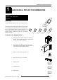
Unpacking and Projector Dimensions 1 UNPACKING & PROJECTOR DIMENSIONS Unpacking Contents of the shipping boxes Dimensions Unpacking To open the banding around the carton, pull out the clip as shown: Take the lower projector cabinet and the upper mirror/screen cabinet out of its shipping carton and carefully place them on a solid level floor. Save the original shipping cartons and packing material, they will come in handy if you ever need to ship your retro projector.
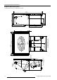
1-2 PROJECTOR RBLD2100 MOUNTING POSITION RBLD2100 MIRROR POSITION 1020mm 40.16" 1341.4mm 52.8" PROJECTOR WEIGHT : 144Kg PROJECTOR SCREEN SIZE : 67" 500mm 19.7" CENTRE OF GRAVITY 1371.4mm 54.0" 1005mm 39.6" 17mm 0.7" 1534mm 60.4" 500mm 19.7" 746mm 29.4" 1020mm 40.16" CENTRE OF GRAVITY 881mm 34.7" Unpacking and Projector Dimensions Projector dimensions (mm/") All measurements shown are in millimeters and inches. 5975968A RETRO DATA 2100LC 130298 1969mm 77.5" 941mm 37.0" 820mm 32.
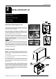
Installation Set Up 2 INSTALLATION SET UP Attachment of the projector Lens Cabinet Assembly Attachment of the Side Profile Mirror Positioning Focusing the Lens 352-(&7,21 +2/( 352-(&725 %$55(/ Attachment of the Projector Lens The projector lens is clamped during transportation inside the lower projector cabinet (lower left back side). Exercise care not to scratch or damage the lens when installing.
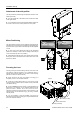
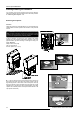
Installation Set Up Attachment of the side profiles The side profiles are packed during transportation inside the mirror cabinet (back side.) The side profiles are to be attached to the forward front sides of the upper cabinet. To fix in position turn in the screws a little and slide the profile over the screws, use the three screws provided for each profile.
Power Up Considerations 3 POWER UP CONSIDERATIONS Preparing your power cord AC Power (mains) cord connection Enabling/Disabling the Password Switching On Projector Status LED Switching To Stand-By / Off Lamp Life Fuses Preparing your power cord Mains power cord with an ANSI 73.
Power Up Considerations Enabling/Disabling the Password It is necessary to remove the projector from the lower cabinet to perform the changing of the pass word function. Follow the procedure for 'Removing the Projector' next. Removing the Projector Attention Follow the procedure as described below, it is recommended that a qualified Barco technician performs the alteration of the password function.
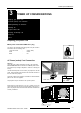
Power Up Considerations b. Once the front panel has been removed the internal projector and loud speakers are visible. The right loud speaker is of significance since, if it is chosen to remove the projector from the front direction, then this speaker must also be removed first. This is done by removing all four of its attachment nuts on the top and right pillars of the lower cabinet structure. b PROJECTOR The rightside panel must next be removed.
Power Up Considerations b. When the leftside panel is completely removed the projector leftside bracket locking screw is visible. Again a mental note of this screws position should be made as it requires undoing in stage b . LEFTSIDE BRACKET LOCKING SCREW The support cross bar at the rear and its attached support cross plate must also be removed by removing their fixing screws.
Power Up Considerations The projector can be removed from the rear (rear slide out position) by pulling and gripping firmly until it is fully out. Gently place the projector on a solid stable surface. Warning: Projector is heavy. ê PROJECTOR REMOVAL POSITION FROM REAR The projector can be removed from the front (front slide out position) by pulling and gripping firmly until it is fully out. Gently place the projector on a solid stable surface. Warning: Projector is heavy.
Power Up Considerations It is necessary to remove the metal cover plate behind which the password strap plug sits. To achieve this remove the four fixing screws and carefully lift clear the cover plate. The password strap on the controller circuit board module will now be visible. The strap plug can be seen approximately half way down on the left side of the circuit board. To change its position just unplug by pulling it out of its pins.
Power Up Considerations Highlight Change password by pressing the control disc up or down and then press ENTER to display the Change Password menu. SERVICE ENTER displays the Change Password menu EXIT returns to the adjustment selection menu. The old password is displayed and can be changed by entering the digit with the numeric keys of the RCU or local keypath. Press ENTER to save the new entered password. Press EXIT if no changes have to be made. IDENTIFICATION CHANGE PASSWORD CHANGE PROJ.
Power Up Considerations Lamp life Lamp reference number description, No-R9829510 : 1000 hrs (standard lamp.) No-R9829600 : (optional long life reduced output wattage lamp.) 2000 hrs in normal mode (575w) and continuous operation. 3500 hrs in economic mode (400w) and continuous operation. 30 hours before the end of lamp lifetime, the following message will be displayed for 1 minute. This message will be repeated every 30 minutes. Press EXIT to remove the message before the minute is over.