
Installation manual
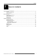
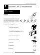
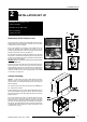
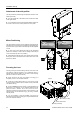
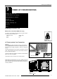
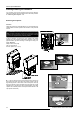

Table Of Contents

Installation Set Up
2-1
5975968A RETRO DATA 2100LC 130298
2
INSTALLATION SET UP
Cabinet Assembly
Attention : Avoid touching the screen while handling the screen
cabinet in order to avoid any damage of the screen surface. Also
exercise caution not to damage the projector lens when joining the
cabinets together.
Lift up the upper mirror cabinet and bring it down vertically onto
the projector lower cabinet.
Both centering pins on the mirror cabinet must match and lock
into the centering holes in the projector cabinet. Ensure also that the
fixing holes in the upper mirror cabinet align with the holes in the lower
projector cabinet.
Once the cabinets are in place, two cabinet attachment screws
are secured (in the fixing holes) from the rear side of the retro
projector. The third is secured by reaching through the lower cabinet
(rear side,) and securing through the far underside of the projection
hole opening. This will require some care in manoeuvring as the fixing
is recessed when the two cabinets are in place. Ensure each screw
is tightened fully by hand.
Attachment of the projector Lens
Cabinet Assembly
Attachment of the Side Profile
Mirror Positioning
Focusing the Lens
Attachment of the Projector Lens
The projector lens is clamped during transportation inside the lower
projector cabinet (lower left back side). Exercise care not to scratch
or damage the lens when installing.
To fix into position it is necessary to first unclamp the lens, by
undoing the clamping screw completely. Lift carefully out by first
pushing it slightly backwards (to clear the clamping hooks) and then
pivoting up the farside of the lens and lifting out.
Take the lens and place through the projection hole on top of the
lower cabinet. The threaded end goes through first. Keep a tight hold
of the lens and carefully lower, the lens and projector barrel will meet
and the two will screw together.
WARNING : ENSURE YOU HAVE REMOVED THE PROTECTIVE PACKING FOAM FROM INSIDE
THE
P ROJECTOR BARREL FIRST.
Screw onto the projector barrel in the clockwise direction ensur-
ing good connection. The lens should screw in without resistance,
if any resistance is felt (the two screw threads are not aligned) then
untighten immediately and remove and try once more. Once proper
connection is made, screw in the lens approximately three quarters
of its length for focusing later.
CLAMPING
SCREW
PROJECTION
HOLE
PROJECTOR
LENS
PROJECTOR
LENS
CLAMPING
HOOKS
&
&