
Installation manual
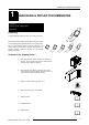
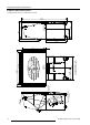
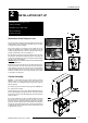
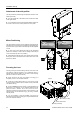
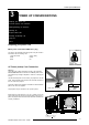
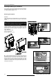

Table Of Contents

Installation Set Up
2-2 5975968A RETRO DATA 2100LC 130298
Attachment of the side profiles
The side profiles are packed during transportation inside the mirror
cabinet (back side.)
The side profiles are to be attached to the forward front sides
of the upper cabinet.
To fix in position turn in the screws a little and slide the profile over
the screws, use the three screws provided for each profile.
Mirror Positioning
The Upper cabinet contains a mirror for reflecting and projecting the
projector image onto the screen. During shipping or storage the mirror
is pivoted into the upper cabinet, and locked by two hand tightable
screws.
To open up the mirror cabinet and locate into the operational
position it is necessary to remove the two locking screws and pull
out the mirror flap fully (as far as possible.)
While holding the flap fully open, lock in position using the same
locking nuts, but this time screw into the screw holes on the outer
sides of the cabinet.
Focusing can only be achieved through access at the rear of the
retro projector, while the projector is in its operational mode. A
projector internal screen pattern may be used to assist focusing
(see Service mode in owners manual.)
Firstly ensure that the outer Front Rotary Lens Ring (a) is
completely turned in the clockwise direction.
Loosen the Locking Fastener Ring (c) of the lens by turning
counter clockwise a sufficient amount to allow turning of the Main
Lens Barrel Tube (b).
Focus the middle region of the screen by turning the Main Lens
Barrel Tube in the clockwise or anti clockwise direction until the
picture is focused. Attention: Do not turn out the lens to far,
otherwise it will fall out of the lens holder. Once the barrel is in the
desired position, lock the Fastener Ring (c) by turning clockwise
until fully locked.
It is now necessary to focus the corners of the picture by
adjusting the Front Rotary Lens Ring (a), moving the desired amount
in the anti clockwise direction.
)
)
Focusing the Lens
Projector
(c) Locking Fastener Ring
(b) Main Lens Barrel Tube
(a) Front Rotary Lens Ring
LOCKING
SCREWS
LOCKING
SCREWS