RVP8 User’s Manual October 2005 3. TTY Nonvolatile Setups TTY Nonvolatile Setups The RVP8 provides an interactive setup menu that can be accessed either from a serial TTY, or from the host computer interface. Most of the RVP8’s operating parameters can be viewed and modified with this menu, and the settings can be saved in non-volatile RAM so that they take effect immediately on start-up. This permits custom trigger patterns, pulsewidth control, matched FIR filter specs, PRF, etc.
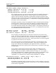
RVP8 User’s Manual October 2005 TTY Nonvolatile Setups Command List: F: Use Factory Defaults S: Save Current Settings R: Restore Saved Settings M: Modify/View Current Settings Mb – Burst Pulse and AFC Mc – Overall Configuration Mf – Clutter Filters Mp – Processing Options Mt – Trigger/Timing Mz – Transmissions and Modulations M+ – Debug Options P: Plot with Oscilloscope Pb – Burst Pulse Timing Ps – Burst Spectra and AFC Pr – Receiver Waveforms P+ – Visual Test Pattern V: View Card and System
RVP8 User’s Manual October 2005 TTY Nonvolatile Setups number of the code that was last saved in the nonvolatile RAM is also shown. This is an improvement over having to check the date of the code to determine which minor release was running. Note that the RVP8 does not actually begin using the current settings until after the “Q” command is entered, so that the processor exits the TTY setup mode and returns to normal operation. 3.1.
RVP8 User’s Manual October 2005 TTY Nonvolatile Setups Diagnostics: PASS If errors were detected by the startup diagnostics then an error bitmask will be shown on the first line. The word “PASS” indicates that no errors were detected. Processes and Threads: RVP8Proc–0 – PID:28503 Priority:10 Policy:RealTimeRR The “Process and Threads” list displays RVP8 processes and their related priority.
RVP8 User’s Manual October 2005 AFC:0.00% (Disabled), TTY Nonvolatile Setups Burst Pwr:–48.6 dBm, Freq:30.000 MHz AFC indicates the level and status of the AFC voltage at the RVP8/IFD module. The number is the present output level in D-Units ranging from –100 to +100. The shorter “%” symbol is used since percentage units correspond in a natural way to the D-Units. Burst Pwr indicates the mean power within the full window of burst samples.
RVP8 User’s Manual October 2005 3.2 TTY Nonvolatile Setups View/Modify Dialogs The M menu may be used to view, and optionally to modify, all of the current settings. The current value of each parameter is printed on the screen, and the TTY pauses for input at the end of the line. Pressing Return advances to the next parameter, leaving the present one unchanged. You may also type U to move back up in the list, and Q to exit from the list at any time.
RVP8 User’s Manual October 2005 TTY Nonvolatile Setups Live Angle Input – 0:None, 1:Sim, 2:TAGS, 3:S/D : 2 This setting is used to configure the input of live angles. In most situations, the angles will be coming in from the RCP via TAGS. The S/D option provides direct conversion of 3–wire synchro waveforms for the AZ and EL position angles. You may directly hookup AZ/EL synchros to the 12–pin input connector on teh IO–62 standard backpanel when you choose S/D.
RVP8 User’s Manual October 2005 3.2.2 TTY Nonvolatile Setups Mp — Processing Options Window- 0:User, 1:Rect, 2:Hamming, 3:Blackman : 0 Whenever power spectra are computed by the RVP8, the time series data are multiplied by a (real) window prior to computation of the Fourier Transform. You may use whichever window has been selected via SOPRM word #10, or force a particular window to be used. R2 Processing- 0:Never, 1:User, 2:Always : 1 Controls R0/R1 versus R0/R1/R2 processing.
RVP8 User’s Manual October 2005 TTY Nonvolatile Setups Minimum freerunning ray holdoff: 100% of dwell This parameter controls the rate at which the RVP8 processes free-running rays. This prevents rays from being produced at the full CPU limit or I/O limit of the processor (whichever was slower); which could result in highly overlapping data being output at an unusably fast rate. Note that this behavior will only occur when running without angle syncing, such as during IRIS Manual and RHI scans.
RVP8 User’s Manual October 2005 TTY Nonvolatile Setups IFD Wide Dynamic Range Parameters Channel separation: 20.00 dB, 0.0 deg Maximum deviation : 0.50 dB, 5.0 deg Overlap/Interpolate interval: 30.00 dB The Channel Separation and Overlap/Interpolate Interval should be determined from the Pr printout described below.
RVP8 User’s Manual October 2005 TTY Nonvolatile Setups Provide WSR88D legacy BATCH major mode: YES Maximum range to unfold: 600.0 km Low–PRF bins range averaged on each side: 2 Overlay power – Refl:5.0dB Vel:8.0dB Width:12.0db LowSamps = ( 0.00000 x HiSamps ) + 6.00 : LowPRF = ( 0.00000 x HiPRF ) + 250.00 : This is actually a fully general implementation of a Lo/Hi Surveillance/Doppler PRF unfolding scheme that provides all of the legacy features as special cases.
RVP8 User’s Manual October 2005 TTY Nonvolatile Setups those transmit polarizations should be used whenever there is more than one choice available. Thus, these selections only apply to the Alternating and Simultaneous transmit modes. Likewise, answering YES to Co-Rcv and/or Cx-Rcv means to use the received data from the co-channel or cross-channel. The receiver question will only appear when dual simultaneous receivers have been configured.
RVP8 User’s Manual October 2005 TTY Nonvolatile Setups Fixed Width Filters (Type 0) These are defined by two parameters. The “Width” sets the number of spectral points that are removed around the zero velocity term. A width of one will remove just the DC term; a width of two will remove the DC term plus one point on either side; three will remove DC plus two points on either side, etc. Spectral points are removed by replacing them with a linear interpolating line.
RVP8 User’s Manual October 2005 3.2.4 TTY Nonvolatile Setups Mt — General Trigger Setups These questions are accessed by typing “Mt” with no additional arguments. They configure general properties of the RVP8 trigger generator Pulse Repetition Frequency: 500.00 Hz This is the Pulse Repetition Frequency of the internal trigger generator. Limits: 50 to 20000Hz.
RVP8 User’s Manual October 2005 TTY Nonvolatile Setups polarization pair may also be used). The control signal will either remain at a fixed level, or will alternate from pulse to pulse with a selectable transition point (See Section 3.2.5). POLAR2 is identical to POLAR1, but may be configured with a different polarity and switch point. This second signal could be used if the radar’s polarization switch required more than one control line transition when changing states.
RVP8 User’s Manual October 2005 TTY Nonvolatile Setups keys in the Pb plot, and will also be slewed in response to Burst Pulse Tracking. Triggers in the second category remain fixed relative to “receiver range zero”, and are not affected by the “L/R” keys or by tracking. This question specifies which triggers are Tx-relative and which are Rx-relative.
RVP8 User’s Manual October 2005 3.2.5 TTY Nonvolatile Setups Mt — Triggers for Pulsewidth #n These questions are accessed by typing “Mt”, with an additional argument giving the pulsewidth number. They configure specific trigger, transmit waveform, and FIR filter properties for the indicated pulsewidth only.
RVP8 User’s Manual October 2005 TTY Nonvolatile Setups processing. Multipliers from 0.0 to +1.0 are generally safe to use because they shift the trigger into the same pulse period that originally defined it. For example, a start time of (0.0 msec + (0.98 * PRT)) would position a trigger 98% of the way up to the next range zero. But, if –0.
RVP8 User’s Manual October 2005 TTY Nonvolatile Setups Range mask spacing: 125.00 meters The range resolution of the RVP8 is determined by the decimation factor of the digital matched FIR filter that computes “I” and “Q”. This decimation factor is the ratio of the filter’s input and output data rates, i.e., the output rate is some integer divisor of the IFD Acquisition Clock (See Mc Section). For the legacy RVP7 IFD operating at its standard frequency of 35.
RVP8 User’s Manual October 2005 TTY Nonvolatile Setups Burst Freq Estimator– Length: 1.33 usec, Start: 0.00 usec This estimator is mostly used with the Pb (plotting commands) and can be referenced in Section 4.3.2. FIR-Filter prototype passband width: 0.503 MHz This is the passband width of the ideal lowpass filter that is used to design the matched FIR bandpass filter.
RVP8 User’s Manual October 2005 TTY Nonvolatile Setups Transmitter phase switch point: –1.00 usec This is the transition time of the RVP8’s phase control output lines during random phase processing modes. The switch point should be selected so that there is adequate settling time prior to the burst/COHO phase measurement on each pulse. This question only appears if the PHOUT[0:7] lines are actually configured for phase control (See Section 3.2.1). Limits: –500 to 500 msec.
RVP8 User’s Manual October 2005 TTY Nonvolatile Setups Bandwidth of transmit pulse: 3.25 MHz Pulselength of transmit pulse: 15.00 usec These questions select the bandwidth and pulse length of the Tx waveform. The bandwidth value represents the true spectrum width of the complete waveform, i.e., including all the effects of whatever frequency modulation and amplitude modulation the waveform happens to use.
RVP8 User’s Manual October 2005 TTY Nonvolatile Setups from –1 to +1 over the complete time duration of the pulse, and whose ordinate ranges from –1 to +1 over the complete frequency span of the pulse. S The class of non-linear FM curves always pass through the points (–1,–1), (0,0), and (1,1), i.e., they begin at the lowest frequency at the start of the pulse, end at the highest frequency when the pulse completes, and pass through the origin (to maintain symmetry across both halves of the pulse).
RVP8 User’s Manual October 2005 3.2.6 TTY Nonvolatile Setups Mb — Burst Pulse and AFC These questions are accessed by typing “Mb”. They set the parameters that influence the phase and frequency analysis of the burst pulse, and the operation of the AFC feedback loop. Receiver Intermediate Frequency: 30.0000 MHz This is the center frequency of the IF receiver and burst pulse waveform.
RVP8 User’s Manual October 2005 TTY Nonvolatile Setups The mean power level of the burst is computed within the narrowed set of samples that are used for AFC frequency estimation. The narrow subwindow will contain only the active portion of the burst, and thus a mean power measurement is meaningful. The full FIR window would include the leading and trailing pulse edges and would not produce a meaningful average power.
RVP8 User’s Manual October 2005 TTY Nonvolatile Setups PLL ratio of (1/1) ==> Input reference at 17.9876 MHz The VCXO phase-locked-loop (PLL) in the RVP8/IFD can work with any input reference clock whose frequency is a rational multiple (P/Q) of half the desired sampling frequency, i.e., the center frequency of the VCXO that is entered in the “mc” command (Section 3.2.1). This question allows this ratio to be established.
RVP8 User’s Manual October 2005 TTY Nonvolatile Setups AFC hysteresis -- Inner: 5.0 KHz, Outer: 15.0 KHz These are the frequency error tolerances for the AFC loop. The loop will apply active feedback whenever the outer frequency limit is exceeded, but will hold a fixed level once the inner limit has been achieved. The hysteresis zone minimizes the amount of thrashing done by the feedback loop.
RVP8 User’s Manual October 2005 TTY Nonvolatile Setups AFC span– [–100%,+100%] maps into [ –32768 , 32767 ] AFC format– 0:Bin, 1:BCD, 2:8B4D: 0, ActLow: NO AFC uplink protocol– 0:Off, 1:Normal, 2:PinMap : 1 The RVP8’s implementation of AFC has been generalized so that there is no difference between configuring an analog loop and a digital loop.
RVP8 User’s Manual October 2005 TTY Nonvolatile Setups PinMap Table (Type ’31’ for GND, ’30’ for +5) ––––––––––––––––––––––––––––––––––––––––––––– Pin01:00 Pin02:01 Pin03:02 Pin04:03 Pin05:04 Pin06:05 Pin07:06 Pin08:07 Pin09:08 Pin10:09 Pin11:10 Pin12:11 Pin13:12 Pin14:13 Pin15:14 Pin16:15 Pin17:16 Pin18:17 Pin19:18 Pin20:19 Pin21:20 Pin22:21 Pin23:22 Pin24:23 Pin25:24 FAULT status pin (0:None): 0, ActLow: NO These questions only appear when the “PinMap” uplink protocol has been selected.
RVP8 User’s Manual October 2005 TTY Nonvolatile Setups Enable Burst Pulse Tracking: YES This question enables the Burst Pulse Tracking algorithm that is described in Section 5.1.4. Remarkably, for such an intricate new feature, there are no additional parameters to configure. The characteristic settling times for the burst are already defined elsewhere in this menu, and the tracking algorithm uses dynamic thresholds to control the feedback.
RVP8 User’s Manual October 2005 TTY Nonvolatile Setups A two-tone simulation will be produced when the RVP8 is setup in dual-receiver mode. The pulse will be the sum of two transmit pulses at the primary and secondary intermediate frequencies. To make the simulation more realistic, the two signal strengths are unequal; the primary pulse is 3dB stronger than the secondary pulse. Frequency span of simulated burst: 27.00 MHz to 32.00 MHz The simulated burst responds to AFC just as a real radar would.
RVP8 User’s Manual October 2005 TTY Nonvolatile Setups The AFC Motor/Integrator feedback loop works properly even if the motor has become stuck in a “cold start”, i.e., after the radar has been turned off for a period of time. The mechanical starting friction can sometimes be larger than normal, and additional motor drive is required to break out of the stuck condition.
RVP8 User’s Manual October 2005 Start bin:0, TTY Nonvolatile Setups Width:10 bins, Bands:16 This question is only asked if we are simulating output rays. The Start Bin chooses the bin number (origin zero) where the simulated bands will begin. The width of each band (in bins), and the total number of bands are also selected. The upper limit for all parameters is the maximum bin count for the RVP8.
RVP8 User’s Manual October 2005 3.2.8 TTY Nonvolatile Setups Mz — Transmissions and Modulations These questions are used to configure the 8-Bit phase modulation codes that may be used to control the phase of a coherent transmitter. The RVP8/Tx will output a pseudo-random sequence of phase codes that are chosen from a specified set of available codes, i.e., all 8-bit patterns that are valid for the phase modulation hardware.
RVP8 User’s Manual October 2005 TTY Nonvolatile Setups 3.3 Advanced Options 3.3.1 * — Sample current noise levels The “*” samples current noise levels from the receiver and then subtracts that noise from subsequent measurements. More information is provided in the Sample Noise Level (SNOISE) section 6–6. 3.3.2 @ — Display/Change current Major Mode This command provides developers with a simple way of switching modes enabling on–the–fly testing of code.