
User's Manual


RVP8 User’s Manual
October 2005
TTY Nonvolatile Setups
3–4
Diagnostics: PASS
If errors were detected by the startup diagnostics then an error bitmask will be shown
on the first line. The word “PASS” indicates that no errors were detected.
Processes and Threads:
RVP8Proc–0 – PID:28503 Priority:10 Policy:RealTimeRR
The “Process and Threads” list displays RVP8 processes and their related priority.
All RVP8 processes/threads should be running under RealTimeRR policy to
guarantee adequate attention from the processors.
Shared library build dates:
This section provides RVP8 developers with information about code resources.
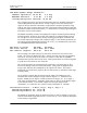
Front panel display:
+––––––––––––––––––––––+
| 0.00 AZ/EL 0.00 |
| FFT 100B 1000Hz x1 |
+––––––––––––––––––––––+
The front panel display mirrors the display on the front of the RVP8 chasis. This is
helpful if you are at a remote location using DspExport.
Tx/Clk:Okay TrigRAM is 99.0% free, TrigCount:378921
The Tx/Clk field displays information about the RVP8/Tx clock (if applicable).
TrigRAM provides resource information for those who are implementing custom
waveforms.
IFD:Okay Link: Delay = 0.541 usec, Jitter = 0.014 usec
This first section of this line summarizes the receiver status and Burst input signal
parameters. The status may show:
Okay RVP8/IFD and connecting cables are all working properly
DnErr Problem in DownLink connection from RVP8/IFD ––> RVP8
UpErr Problem in UpLink connection from RVP8 ––> RVP8/IFD
NoPLL RVP8/IFD PLL is not locked to external user-supplied clock reference
DiagSW RVP8/IFD test switches are not in their normal operating position
The section second describes the IFD link status. During startup the RVP8 measures
the round trip delay along 1) the uplink to the receiver module, 2) the pipeline delays
within the receiver module, 3) the downlink, and 4) pipeline delays in the data
decoding hardware. The time shown is accurate to within 14ns, and is used internally
to insure that the absolute calibration of trigger and burst pulse timing remains
unaffected by the distance between the main card and the receiver module. You may
freely splice any lengths of cable without affecting the calibrations; the delay time
will change, but the trigger and burst calibrations will remain constant.
The standard deviation of the measured delay is also shown. If the link to the IFD is
working properly this variation should be less than half the period of its acquisition
clock. Larger errors may indicate a problem in the cabling. A diagnostic error bit is
set if the error is greater than two acquisition clock periods.