
User manual


V 1.0 30.04.2012 13 / 15
CHROMOFLEX
®
Pro
1 Kanal / 2 Kanal
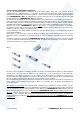
Fig. 7
Note maximum load: at 350mA 12 LEDs can be connected in series (having 3.5 Volts for white, this may result
into 42 Volts, so that the perfect supply voltage would be 46V). At 700mA higher power dissipation is produced
on the PCB. Max. 6 LEDs per channel can be connected in series. Otherwise electronics may break down or will
be destroyed by overheating.
7. Operation
Please operate this unit only, when it is working properly.
In case of an error, switch off the unit immediately. Do not operate the unit, until the unit was verified
electronically by a qualified electrician.
A case of error is:
- visible signs of damage on the unit
- the unit is not operating properly
- fume rising or crackling sounds from the unit
- visible signs of overheating
Maintenance and service which require access to live components inside the unit must be carried out by an
authorized electrician.
Warning: risk of electric shock!
How to avoid malfunctions or fire risk:
- Do not affect air circulation by covering the unit.
- Do not attach anything to the unit e.g. decoration items etc.
Do not let your children play unattended with electrical equipment. Children cannot always perceive possible
d
angers correctly.
7.1 Start-up
Connect LEDs and power supply as shown in fig. 3, 4 and 6. Make sure that LED-stripes are connected to
CHROMOFLEX
®
Pro
CV or Power LEDs are connected to
CHROMOFLEX
®
Pro
CC and the correct power
supply was chosen. At first a test is performed on the module starting with the first channel (called CW)
changing softly to the second channel (called WW), followed by a short break. The 1 channel dimmer has the
same start up program - therefore in this case the break is much longer.
Diagnostic LED: The modules are equipped with a small LED. For regular operation this LED will change every
5 seconds and flickers when data is transmitted over the bus.
Each module is shipped with several effects: user programmes, random effects, editable color tablets, fixed
colors, etc. For more details please refer to the manual of the remote control and software for Pro USB Dongle
(for PC) at: www.barthelme.eu