
Operation Manual


EN
page 28
INSTALLER SECTION
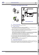
2. DETERGENT DISPENSER INSTALLATION
A
B
C
min 3
cm
Point B
pict. 6
GERMAC
15185
Ø 8
SEKO
15108/E
Ø 10
CONNECTION DIAGRAM
pict. 5
2.1 Electrical connection
Follow the wiring diagram attached to the machine.
2.2 Water connection
a) A Ø12 hole must be made on the back of the appliance.
In some appliances the hole has already been made and is closed with a plastic cap.
Remove the cap from the hole and t the delivery connection.
b) Otherwise, drill one of the same diameter as the injector on the back part of the tub (see
pict. 5. This operation must be carried out by the Technical Service.
The hole must be made above the water level.
Important: make the hole in a position distant from the overow tube, so that detergent
does not ow out immediately. Fix the dispenser in a vertical position with tube connectors
turned downwards, making sure not to place it on energized components.
Clean the inside of the machine from any drilling residual.
c) Correctly mount the injector (C) using the appropriate xtures.
d) Connect the suction tube to the suction attachment of the dispenser (see pict. 5 point A).
e) Connect the delivery tube to the other attachment of the dispenser, and the delivery tting
(see pict. 5 point B).
f) Insert the suction tube with lter in the detergent tank.
g) Prime the detergent and proceed to dispense.
2.3 Dispensing the detergent
The detergent dispenser capacity can be adjusted using a screwdriver as shown in pict. 6.
Every 2 cm of product drawn into the tube corresponds to 0.25 cm³ equivalent to 0.3 g (with
a concentration of 1.2g/cm³). For proper dispensing see paragraph 5.1.