
Operation Manual


EN
page 26
INSTALLER SECTION
C
D
B
A
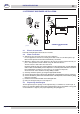
code 10799
pict. 2
PROBLEMS CAUSES AND SOLUTIONS
Water exits from the rinse aid suction tube. The suction valves 10805 - 10705/D and delivery do not seal due to
foreign bodies in the closing seats.
Clean the valves 10805 - 10705/D, check that the rinse aid suction
lter is present, and lter the water entering the dishwashwer.
The dispenser does not draw rinse aid. a) the delivery valve 10805 - 10705/D does not seal due to foreign
bodies in the closing seats.
Clean the valve 10805 - 10705/D, check that the rinse aid suction
lter is present and lter the water entering the dishwasher.
b) The piston seal 10806 does not hold because it is damaged.
Replace the seal 10806 with an original.
c) check the diaphragm 10807 - 10705/O.
code 10799/G
pict. 3
C
D
B
A
Feed cable: the retailer - importer - installer must ensure that the feed cable complies
with the cable insulation category of the workplace, in conformity with current Technical
Standards.
1.4 Temperature adjustment
If necessary, the water temperature of the wash and rinse cycles can be adjusted by means
of the ne-adjustment screws on the respective thermostats.
The recommended temperatures are 55°C for the wash cycle (tub) and 85 - 90°C for the
rinse cycle (boiler). Machines with boiler inside the washing tub have only one thermostat
which should be set at 75-80°C.
1.5 Rinse aid dispenser operation
Technical characteristics
Operation: It utilizes the difference in combined pressure caused by turning the washing
pump on and off, and the rinse pressure.
Water connection:
1) Connect the dispenser tube tting (A) to the pump, by means of the rubber tube installed
in the appliance (pump pressure).
2) Connect the small black rubber tube by the brass delivery tting (B) to the connection in
the boiler (injector).
3) Make sure that the green product suction tube is inserted on the special tting (C) and
that the small lter and the ballast are inserted in the rinse aid tank.
Priming: To prime the dispenser, turn on the appliance and carry out several complete wash
cycles or press the adjustment screw (D) during the wash cycle and open and close the door
combined with pressing the pin (D). This method speeds up the rell process.
Adjustment: With each rinse cycle, the dispenser draws an amount of rinse aid, adjustable
from 0 to 4 cc, equivalent to a length of 0 to 30 cm drawn into the suction tube.
In order to regulate the dispenser to the minimum amount, turn the adjustment screw (D)
completely clockwise. For the maximum amount, turn the screw anticlockwise about 20
complete turns.
For the correct amount of rinse aid, see the paragraph “Use of rinse aid”.(chap. 5.2).
N.B.: for each turn of the screw the amount of the product drawn into the tube varies by 1.6
cm, equivalent to 0.2 cm³/turn (about 0.21g/turn with a concentration of 1.05 g/cm³ of rinse
aid). The rinse aid cannot function properly if the difference in level between the bottom of
the machine and the container exceeds 80 cm.
THE DISPENSERS ARE PRE-SET TO A 5 CM OF TUBE (0,65 gr.) INTAKE OF PRODUCT
FOLLOWING A TEST PHASE SYSTEM CHECK. THIS MEASUREMENT SHOULD
BE ADJUSTED ACCORDING TO THE TYPE OF RINSE AID USED AND WATER
HARDNESS.