INSTALLATION INSTRUCTIONS UNIT No. 2850/3850 CELESTA 3/8” FRAMELESS SLIDING ENCLOSURE QCI0017 Rev.
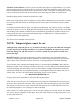
INSTALLATION NOTES: Unpack your unit carefully and inspect for freight damage. Lay out and identify all parts using the instruction sheet as a reference. Before discarding the carton, check to see that no small hardware parts have fallen to the bottom of the box. If any parts are damaged or missing, refer to the descriptions noted in the instructions when contacting your dealer for replacements. Handle the glass panel(s) carefully and protect the edges.
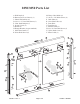
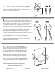
2850/3850 Parts List A. Wall Jamb (2) B. Bottom Track (w/ silencer) (1) C. Plastic Wall Anchor (6) D. #8 x 1 1/2” Truss Head Screw (6) E. Clear Jamb Bumper (6) F. Nylon T-Lock (2) G. Header (1) H. Hanger Bracket (4) (pre-attached) J. Glass Door Panel (2) K. Glass Hole Sleeve (4) M. Heavy Glass Roller (4) N. #8-32 x 3/8” Roller Screw (4) P. Back Plate (4) R. Clear Plastic Disc (8) S. Front Plate U. Towel Bar (2) V. Bottom Guide (3) W. #6 x 3/8” Pan Head Screw (3) X. Nylon Jamb Cover (2) Y.
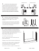
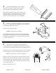
SHOWER HEAD LEFT 1 SHOWER HEAD RIGHT The 2850/3850 Celesta sliding enclosure is supplied with pocketed wall jambs [A]. The jambs are notched on both ends to fit over the bottom track. It is important to determine the proper orientation of the unit before marking and drilling the walls. For maximum waterproofing, position the “open” pocket of the wall jamb to the interior for the shower head wall. This will force the interior panel to be on the shower head side.
4 Before replacing the track, force a slight downward bow into it. This will ensure that the track fits tight to the threshold in the middle. SIL ICO NE Run a bead of silicone on both flat surfaces on the bottom of the track. Then replace the track onto the threshold using the pencil marks from step #3 as a guide. Be sure the raised side is on the exterior. 5 Replace one wall jamb and attach it to the wall with the #8 x 1 1/2” truss head screws [D].
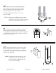
7 Attach the four black heavy-duty roller bearings [M] to the door hanger brackets [H] as shown using the #8-32 x 3/8” hex head screws [N]. The rollers should be approximately in the center of the slots of the bracket fins. 8 Place one panel [J] on the inside of the shower/tub with the rollers facing the back wall and the textured side of the panel facing the outside (if applicable). Set it on a drop cloth or piece of cardboard to protect the glass and the shower/tub surface.
10 Place one of the clear bottom guides [V] in the middle of the tub track as shown. Using the hole in the back of the bottom guide, drill a 1/8” hole into the inside of the tub track. Attach the bottom guide with a #6 x 3/8” pan head screw [W]. OPTION: There are two additional bottom guides included in the hardware. These can be installed for additional strength and stability. Follow the previous instructions to do so.
Neatly silicone each end of the tub track where it fits into the wall jambs as well as the seam between the wall and the wall jamb and the curb and threshold on the inside of the shower. SIL IC ON E SIL IC ON E 13 NOTE: Silicone on the exterior seam is optional. NOTE: DO NOT USE the shower until the silicone is completely cured. Check the tube of silicone for the manufacturer recommended cure time.