
Instructions
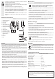
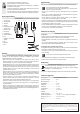

Operating elements
9
7
12
3 7 8 9
10
65421
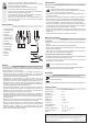
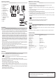
1 Front protective cage
2 Fastening clip
3 Cap nut
4 Rotor blade
5 Mounting ring for rear
protective cage
6 Rear protective cage
7 Rotor shaft
8 Motor housing
9 Oscillation switch
10 Function switches
11 Stopper ring for height
adjustment
12 Standpipe
13 Cover
14 Stand
11
12
13
14
Assembly
Carefully unpack the product and remove the packaging. Arrange the individual parts on a
clean surface and check that all parts shown above are present (refer to "Operating elements").
• Loosen the four screws on the stand legs (14) and then remove them. Place the legs in a
cross shape and place the standpipe (12) onto the stand legs. Reinsert the screws and then
tighten them. Place the cover (13) onto the stand legs so that the screws are covered.
• The motor housing (8) and function switches (10) form a single unit. Loosen the xing screw
at the bottom of the housing unit until it ts onto the standpipe. Do not loosen the xing screw
completely to prevent the nut from falling out. Turn the xing screw anticlockwise to loosen it.
Place the housing unit on the standpipe and turn the xing screw clockwise to x it into place.
• Place the rear protective cage (6) onto the cams on the motor housing. The openings on the
rear protective cage must t exactly onto the cams. Place the mounting ring (5) over the rotor
shaft (7) onto the thread on the motor housing, then turn it clockwise until the rear protective
cage sits securely.
• Place the rotor blade (4) onto the rotor shaft so that the slots on the rear side t onto the pins
on the rotor shaft. Fix the rotor blade in place using the cap nut (3). Hold the rotor blade in
place with one hand and turn the cap nut anticlockwise until it is secure.
• Check that the rotor blade rotates properly by turning it with your hand. Ensure that there is
no friction; if so, repeat the previous steps again.
• Hang the front protective cage (1) on the rear protective cage and close the clips. Ensure that
the holes for the safety screws are aligned with each other. Secure the safety screws into
place using a Phillips screwdriver. Place the nut (included with the product) on the opposite
side to tighten the screws.
Operation
Place the fan with the stand (14) on a dry, clean, horizontal and secure surface.
Keep the fan away from devices that generate heat.
Do not place the product under vases or owerpots to prevent water dripping
onto the product.
• Ensure that the fan is placed on a at and stable surface to prevent accidents.
• Ensure that the fan is turned off. Press the function switch 0 (10) to turn the fan off. Insert the
mains plug into a suitable mains socket.
• Set the desired fan speed using the function switches 1/2/3:
1 = low fan speed, 2 = medium fan speed, 3 = high fan speed.
• Change the air ow by carefully moving the motor housing up or down. Do not use excessive
force when moving the motor housing. Do not attempt to move the motor housing further
than it is intended to go.
• Push the oscillation switch (9) downwards. The fan swivels left and right. Pull the oscillation
switch upwards to stop the oscillation.
• Press the function switch 0 to turn off the fan.
Maintenance and cleaning
a) General information
• Turn off the fan before cleaning and remove the mains plug from the mains socket.
• Do not use any abrasive or chemical cleaning materials.
• Wipe the fan components (only the protective cage and the stand) regularly with a dry
dustcloth.
• If you are not going to use the product for a long time, cover it and store it in a dry location
away from direct sunlight.
b) Cleaning the rotor blade and protective cage
• If a signicant amount of dust accumulates on the rotor blade (4), the fan can be disassembled
by following the steps in "Assembly" in the reverse order.
• The rear and front protective cages and the rotor blade can be wiped clean using a slightly
damp cloth.
Danger of injury! The rotor blade has sharp edges.
• Dry all components carefully after cleaning and before reassembly.
• Assemble the product as described in the "Assembly" section.
Disposal
Electronic devices are recyclable waste and must not be disposed of in the
household waste.
At the end of its service life, dispose of the product according to the relevant
statutory regulations.
You thus full your statutory obligations and contribute to the protection of the environment.
Technical data
Operating voltage ................................. 220 – 240 V/AC, 50/60 Hz
Power consumption .............................. 45 W
Protection class .................................... II
Oscillation range ...................................Approx. 85 °
Tilt angle ............................................... Approx. 25 °
Cable length .........................................Approx. 1.6 m
Cage diameter ...................................... Approx. 43 cm
Air ow rate ...........................................Approx. 3507 m³/h
Speed levels ......................................... 3
Height adjustment .................................105 – 125 cm
Operating/storage conditions ................-5 to +45 °C, 0 – 95 % RH
Dimensions (L x W x H) ........................ Approx. 62 x 62 x 125 cm
Weight ..................................................approx. 2.5 kg
This is a publication by Conrad Electronic SE, Klaus-Conrad-Str. 1, D-92240 Hirschau (www.conrad.com).
All rights including translation reserved. Reproduction by any method, e.g. photocopy, microlming, or the capture in
electronic data processing systems require the prior written approval by the editor. Reprinting, also in part, is prohibited.
This publication represents the technical status at the time of printing.
Copyright 2018 by Conrad Electronic SE. *1619407_v1_0118_02_hk_m_GB