
Manual

ISI34, ISI35
10 www.baumer.com
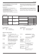
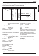
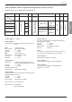
Input specification, terminal assignment and adjustable time ranges (AC versions)
The time range is set via a control input (screw terminal 5).
S
crew terminal
No. 1
I
NP A
AC/DC
No. 2 No. 3
I
NP B
AC/DC
No. 4 No. 5 No. 6 No. 7 No. 8
I
SI34.013AX01
ISI35.013AX01
Timer Enable Input AC/DC
Common connection for INP A
and INP B
R
eset
Enable
NPN reset key locking input,
Contact with GND. key free.
not
a
ct
iv
e
=
99999 h 59 m
not active
=
9999 h 59 m 59 s
GND = 0 V DC
Backlighting (–)
Backlighting (+)
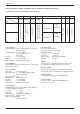
Screw terminal 1:
Timer Enable Input: time measurement as long as the level at
this input is high.
Optocoupler input 10 ... 260 V AC/DC
galvanic isolation, active for
high signal
Low level: 0 ... 2 V AC/V DC
High level: 10 ... 260 V AC/DC
Input resistance: approximately 160 kOhm
Screw terminal 2:
Common AC/DC, common connection for the optocoupler inputs
(screw terminals 1 and 3)
Screw terminal 3:
Reset input: active for high level.
Optocoupler input: 10 ... 260 V AC/DC galvanic isolation,
active for high signal
Min. pulse duration: 16 ms
Max. frequency: approximately 30 Hz
Low level: 0 ... 2 V AC/V DC
High level: 10 ... 260 V AC/DC
Input resistance: approximately 160 kOhm
Screw terminal
4:
Electrical locking of the reset key Contact input / Open Col-
lector NPN (switching at 0 V DC)
Low level: 0 ... 0,7 V DC
High level: 3 ... 5 V DC
Input resistance: approximately
2,2 MOhm
Input not active: Reset key locked
Input in contact with GND:
Reset key unlocked
Screw terminal 5:
Time range switching (Mode)
Contact input / Open Collector NPN
(switching at 0 V DC)
Low level: 0 ... 0,7 V DC
High level: 3 ... 5 V DC
Input resistance: approximately 2,2 MOhm
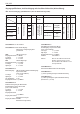
Function: see table 3
Remark:
If the time range is changed during operation,
the device must be
reset, otherwise the counting value will not be reproducible.
Screw terminal 6:
Common GND connection for screw terminal 4 (reset key
locking input) and screw terminal 5 (time range switching).
Screw terminal 7:
(–) external power supply for the backlight option
Screw terminal 8:
(+) external power supply for the backlight option
(24 V DC ±20 %, 50 mA)
d
esignation
M
odel
C
ommon
AC/DC
T
ime range (Mode) GND BL
–
B
L
+
reset input AC/DC
Table 3
contact with
G
ND
=
99999,99 h
contact with
GND
=
9999999,9 s