
Manual

ISI34, ISI35
8 www.baumer.com
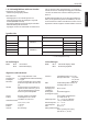
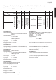
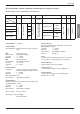
Model Operating mode Inputs
INP A INP B
ISI34.010AX01
ISI34.011AX01
ISI34.013AX01
ISI35.010AX01
ISI35.011AX01
ISI35.013AX01
Timer –– 00 ... 0,7 V DC
Timer ––
10 ... 260 V AC/DC
04 ... 30 V DC
10 ... 260V AC/DC
00 ... 0,7 V DC
04 ... 30 V DC
10 ... 260 V AC/DC
DC operating modes:
Timer: INP A: no function
INP B: Timer-Enable-Input
AC operating modes:
Timer: INP A: Timer-Enable-Input AC/DC
INP B: reset input AC/DC
Table 1
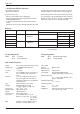
Time range
99999h 59 m/
99999.99 h
9999 h 59 m 59 s/
9999999.9 s
10 ... 260 V AC/DC
NPN
PNP
AC/DC
NPN
PNP
AC/DC
AC/DC
AC/DC
Options: x = A: no backlight
x = B: with backlight
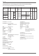
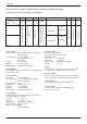
Main technical features:
Display: LCD, 8 decades, height of the figures 8 mm
Display range: 0 ... 99999999 with leading zeros
suppression.
Accuracy: < 100 ppm
Note: For one ON/OFF-cycle the counter can lose
max. one impulse of the selected time
range
Overflow: In case of a display range overflow, the
timer starts again from 0, but without
removing the leading zeros and activating
all decimal points.
Keys: Electrical locking of the reset key
Housing: Panel mounting, 48 x 24 mm
according to DIN 43 700, RAL 7021
Panel cut-out: 22,2
+0,3
x 45
+0,6
mm
Mounting depth: approximately 48 mm
Weight: approximately 50 g
Protection level: IP65 on the front side
Connection: Screw terminals, RM 5.00, 8 poles
Rated cross-section: max.: 1 x 1,5 mm
2
2 x 0,75 mm
2
AWG 26-14
EMC: Interference emissions EN55011 Class B
Interference resistance EN 61000-6-2
Device safety:
Design to: EN61010 Part 1
Protection Class: 2
Application area: Soiling Level 2
Power supply: Non-replaceable lithium battery
(lifetime approximately. 8 years at 20°C)
Working temperature:
–10 ... +55 °C, relative humidity < 85%,
without condensation
Operating temperature:
–10 ... +60 °C
Storage temperature:
–20 .. +70°C
Altitude: to 2000 m
Backlighting: must be powered by an external elecrical
source (24 V ±20%, 50 mA)
Overview
1.10 Failure possibilities and causes
Impossible to use the keys:
-
Key lock input activated
Counter does not count:
- Wrong or reversed wiring of the counting input
- Setting of an input signal not matching the pulse generator
- Polarity (NPN/PNP) reversed
- No ground connection between the pulse generator and the
c
ounter
-
Signal levels do not reach the switching threshold of the counter
I
f, despite all, your device still does not operate, contact your
local representative or call us directly for technical support.
W
hen sending your device back, please attach a short descrip-
t
ion of the failure, of the programming and of the connection
diagram, in order to allow us to reproduce a possibly existing
d
efect and to repair your device as quickly as possible.