
User guide


TP10330 8
KIT INSTALLATION
CAUTION: BE SURE THE FOLDER IS TURNED OFF
AND UNPLUGGED FROM THE AC POWER BEFORE
REMOVING ANY GUARDS AND STARTING THE IN-
STALLATION.
WARNING: IT IS RECOMMENDED THAT YOU HAVE
A QUALIFIED SERVICE PERSON PERFORM THE FOL-
LOWING PROCEDURE BECAUSE OF THE DANGER
FROM HAZARDOUS MOVING PARTS, ELECTRICAL
SHOCK (SEE CAUTION ABOVE) AND DAMAGE TO
THE FOLDER. HOWEVER IF YOU WISH TO PRO-
CEED ON YOUR OWN, USE EXTREME CARE.
BAUMFOLDER CORPORATION ASSUMES NO RE-
SPONSIBILITY FOR DAMAGE CAUSED TO YOUR
FOLDER OR PERSONAL INJURY.
1. Remove the infeed table air and vacuum hoses from
the manifold block on the right side of the folder frame. Note
the orientation of the hoses for re-installing.
2. Remove the infeed table and carefully lay it upside
down on a stable flat surface.
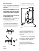
3. Apply a strip of Teflon tape to the threads of the
plastic elbow adapters. Screw them into each side of the
solenoid valve so that the barbed end are out towards the
electric junction box. Remove the two top bolts(when IN is
to your left) and attach the monuting bracket.(Figure 1)
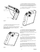
4. Carefully remove the two metric socket head cap
screws and mount the vacuum solenoid assembly.(Figure 2)
Re-insert and tighten the two metric socket head cap screws.
Figure 1
5. Remove the vacuum hose from the adapter on the
vacuum feed wheel assembly and replace with the shorter of
the new hoses. The loose end of the new hose is to be
attached to the adapter on the IN side of the vacuum
solenoid. Attach the other new hose to the OUT side of the
vacuum solenoid, add the manifold adapter from the old hose
to the loose end.
6. Remove the four screws that attach the right side cover
to the frame. Carefully remove the right side cover. You will
notice that the air and vacuum hoses inside the cover will need
to be removed from the manifold block. Observe which hose
goes to which adapter on the block, and remove them.
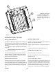
7. Lay the right side cover on a protected flat surface so
that you do not scratch or mar the plastic surface. You are
now going to use the mounting block to locate the
holes(Figure 3) that you will need to drill for mounting the
counter support assembly. After marking the holes, remove
the backing plate and drill your four holes using a 0.217 drill
bit.
METRIC CAP SCREWS
Figure 2