
User guide


9 TP10330
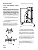
Figure 3
8. Mount the swivle base to the outside of the side guard
using the four screws provided(Figure 4).
Warning: Make certain that the swivel base is below the
radius of the curve of the side guard or beakage of the
guard could take place.
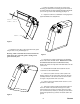
min=0.125"
max=0.250"
max=0.250"
9. Remove the thumb screw on the top section of the
mounting post and insert the mounting post on the bottom of
the counter fully into the hole. Reinstall and tighten the thumb
screw in the top section of the mounting post(Figure 5).
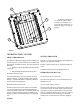
10. Adjust the counter for a comfortable viewing angle and
tighten all thumb screws and jam nuts.
Figure 4
11. Reconnect the air and vacuum hoses to the manifold
block on the side of the folder frame. Double check to make
sure that the hoses have been reconnected correctly.
Replace the guard to the right side of the folder and secure the
cover screws.
12. Reinstall the infeed table and re-attach the air and
vacuum hoses to the manifold block.
13. Connect the scanner connector (white nylon) to the
matting connector on the counter then connect the solenoid
assembly connector to the circular connector on the counter.
See Figure 6 for placement of the scan sensor.
14. Connect (plug in) the folder and the counter to a well
grounded 115 VAC outlet.
15. Turn on the counter with the switch located in the rear
of the unit. NOTE: The solenoid will energize for a short
period each time the counter is turned on. Reset the counter
(see reset instructions). Thank you, and enjoy the convenience
and increased productivity your DCU-600 batch counter will
provide.
Figure 5