Installation Instructions ZTX6/8M2, ZTX6/8M2/J ZTX6/16M4, ZTX6/16M4/J ZTX6/24M6, ZTX6/24M6/J ZTX6/32M8, ZTX6/32M8/J ZTX6/STD These instructions cover installation for the Installer.
BLANK HBZTX6-IN-4 Page 2
Contents 1 Important Safeguards 1.1 1.2 1.3 1.4 Safety Damage Requiring Service Safety and Electromagnetic Compatibility (EMC) Manufacturer’s Declaration of Conformance 5 6 6 7 7 2 Instruction Manuals 7 3 Unpacking 8 4 Accessories 9 5 Description 10 6 Installation 12 6.1 6.2 6.3 6.4 6.5 6.6 6.
9 The Menus 9.1 9.2 9.3 9.4 9.5 9.6 9.7 9.8 9.9 9.10 9.11 9.12 9.13 9.14 9.
1 Important Safeguards This product is exclusively for use in CCTV applications and has no other purpose. Read and Retain the Instructions - All the safety and operating instructions should be read before the unit is operated and should be retained for future reference. Cleaning – Disconnect the power before cleaning. Do not use liquid cleaners or aerosol cleaners. Use a damp cloth for cleaning.
Object and Liquid Entry – This equipment must be protected from the ingress of foreign materials. Never push objects of any kind into this unit through openings as they may touch dangerous voltage points or short-out parts that could result in a fire or electric shock. Never spill liquid of any kind on the unit. Servicing – There are no user-serviceable parts. Do not remove the covers as this may expose you to dangerous voltages or other hazards, including moving mechanical parts.
1.3 Safety and Electromagnetic Compatibility (EMC) Do not operate the unit outside the voltage and temperature limits given in the specification. WARNING To reduce the risk of electrical shock, do not open covers. There are no user serviceable parts inside. Refer servicing to qualified service personnel. This product is intended for use in general-purpose CCTV applications in a residential, commercial or light industrial EMC environment.
3 Unpacking Keep your packaging for use if your ZTX6 is stored for a time or needs to be returned for whatever reason.
4 Accessories ZTX6/MOD This is an additional 8 camera-input, 8 alarm-input, 2 monitor-output module. Adding subsequent ZTX6/MODs to an 8M2 converts it to a 16M4, 24M6 then a 32M8. The maximum configuration for the ZTX6 is 32M8. Do not exceed this. ZTX6/RMA3 The ZTX6/32M8 is 19” 3U standard rack mounting, all the smaller units are not unless fitted to a ZTX6/RMA3 (Rack Mount Accessory, 3U). The ZTX6/RMA3 is a steel plate with countersunk holes and screws to allow the attachment of a ZTX6.
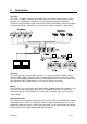
5 Description The ZTX6 The ZTX6 is a modular switching matrix which transmits coaxial-telemetry to the camera positions. It is controlled by a keyboard. You should read the keyboard installation instructions for information on how to connect the ZTX6 to the BaxNet network (the network over which the ZTX6 is controlled). A schematic for a simple installation is shown below.
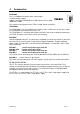
Responses Responses define what will happen when an alarm occurs. Many responses can be defined and any alarm input can have any response allocated to it. An event message received over the network can also call a response. A response can broadcast an event message onto the network. In this way, the alarms across several units can operate together.
6 Installation 6.1 Assembly Assembling the main unit from a combination of ZTX6/MODs and a ZTX6/8M2 is described in the ZTX6/MOD instructions included separately with every ZTX6/MOD. 6.2 Video Connections - Standard All video must be 1 V pk-pk composite via 75 ohm coaxial cable with BNC connectors. • Connect coaxial cable terminated with BNC connectors from your ZTX6 camera inputs to your cameras or receivers (refer to receiver manual).
6.4 Alarm Input Connections The ZTX6 has the same number of alarm inputs as camera inputs (they are not dedicated to the corresponding camera input). On each module they are numbered on the graphic from 1 to 8 (see Figure 5 on page 17). They are actually numbered in the same way as the cameras, the base unit (ZTX6/8M2) contains inputs 1 to 8, the first additional module (ZTX6/MOD) contains inputs 9 to 16 (but labelled 1 to 8), the second 17 to 24 and the third 25 to 32 (see Figure 5).
6.6 Connecting the Network Keyboard These are described in the keyboard instructions as are the BAX-RKIT for expanding the network. Connect the keyboard using the RJ45 connector. CAUTION: Each of the modules on your BaxNet network have an address. If two units share the same address then the network will not work. The ZTX6 address is set in the on-screen menus. The keyboard has built in network termination and/or biasing.
(The number 1.xx indicates the ZTX6 software version, usually different from the ZKX2) Notice also that the Unit ID for your ZTX6 is displayed here. Make a note of it. • Check that your connections are correct by running through the tests outlined in the next section.
7 Testing Your Installation (Basic Operations) 7.1 The ZKX2 Keyboard Your ZTX6 can be operated using the ZKX2 and ZKX2/J keyboards. The key functions are shown below. Your ZTX6 will operate with ZKB1 keyboards in addition to ZKX2 keyboards. However, proportional control is only available with the ZKX2/J keyboard when used with ZTX6 v1.04 software or above.
7.2 Selecting your ZTX6 If you are installing 2 or more ZTX6s on the network then connect them one at a time and change the Unit ID (see section 9.15 on page 37) so that they do not clash. The current ZTX6 Unit ID is displayed on power-up. ZTX6 MKII VERSION : 1.xx BY BAXALL SECURITY LTD UNIT ID 9 FIRMWARE VER : wwxxyyzz To select your ZTX6 the first time you power up • Enter the Unit ID number followed by + . Your keyboard should now be controlling your ZTX6.
7.4 Selecting a Camera The cameras are numbered as shown in Figure 5. • Select a camera by entering the camera number and pressing 7.5 . Starting A Sequence On The Current Monitor Once the sequences have been set up in the menu system. • Start the sequence by entering the sequence number and pressing • Stop a sequence by selecting a camera 7.6 To Operate The Telemetry Select a monitor and a camera as shown above, ensure that a sequence is not running and press any telemetry key.
8 Using The On-Screen Menus 8.1 Introduction The menus are used to configure your ZTX6. The main menu is shown below followed by a brief description of each of the sub-menus. 0 Main menu Set new password menu Alter sequence menu Camera/Rx menu Alarms menu System settings menu Keyboard menu Installer setup menu Exit menu Set new password menu Change the operator and/or installer passwords. Alter sequence menu Set up the camera sequences with lists of cameras and dwell times. There are 8 sequences.
Installer setup menu This menu is only active if you have entered under the installer password. It displays the software and firm-ware version numbers (also displayed on power-up). It also allows you to view and set the Unit ID, store and restore user defaults and set the ZTX6 to factory defaults.
8.3 Entering The Menu System The menu system is entered using the menu key and the Shift key key and the Menu key then enter your 4 digit password at the prompt: . Press the Shift Password Validation **** Enter Password If your password is incorrect then the following message is displayed. Password Validation Enter Password **** Validation Failed Hit ENTER to continue Press the ENTER key and try again. 8.
8.6 Changing Fields With A Set List Of Options Fields which contain a list of options are capitalised. For example in Figure 6 the fields ‘Input preset’, ‘Rx attached’, ‘Telemetry mode’ and ‘Preset mode’ all have a list of options which are accessed using the left-arrow and right-arrow keys (see section 9.3 for details of the options). 3 Camera/Rx menu Camera number : Title Camera 19 Input present : Rx attached : Telemetry mode : Preset mode : 19 YES YES STANDARD ENHANCED return to main menu Figure 5.
8.8 Paging Between Screens The sequence menu shown in Figure 7 is different for each sequence (Sequence number 5 is shown). To move between sequences either: • Type a new sequence number, or, • Use, page-up (while holding press the up-arrow, or up Joystick) or press the down-arrow, or down Joystick) page-down (while holding These move to the next/ last sequence and apply to other screens which have this format such as the Camera/Rx menu in Figure 6.
9 The Menus 9.1 Change Password Menu CAUTION: Do not lose or forget your installer password because restoration of your system may entail a visit by an Engineer. To change the passwords: • Select ‘Set new password menu’ using the up-arrow/down-arrow (or joystick) to highlight then the Enter key to select. 1.
9.2 Sequences Menu The sequence menu is different for each of the 8 sequences (sequence number 5 is shown).
The factory default setting is with sequences 1 and 2 defined already as, respectively, cameras 1 – 16 and cameras 17 – 32, all with a dwell time of 5 seconds. The other sequences are undefined. 9.3 The Camera/Rx menu Where Rx = receiver. Use and up-arrow or Joystick (together) or step through the camera inputs. and down-arrow or Joystick (together) to The line below the word Title can be edited using the text editor - see Section 8.7, Entering And Changing Text.
9.4 Alarm Main Menu This menu and its sub-menus are concerned with alarms and network events. 4 Alarm main menu Global alarm setup Alarm responses Event responses Alarm monitors Alarm input senses Alarm output senses Return to main menu Alarms are triggered by the alarm inputs. Network Events are received from other units over the network. Each alarm (max 32) or event (1 to 255) can be mapped to a response.
9.5 Global Alarm Setup Menu This menu controls the overall alarm setup, how all the responses are reset, and the system state to be returned to once all the responses are clear. 4.1 Global alarm setup menu Mode :SWITCH Response mode :ACK End action :NONE Timeout time :020s Transp. mode timeout :005s Return to alarm main menu There are 5 display mode settings NONE, LAST, STACK, SWITCH and ROTATE. These modes change dependent on the response modes which are ACK, TRANSP., and TIMEOUT.
STACK = As each response arrives it is shown on the next available alarm-monitor (according to the alarm monitor list, section 9.10). Once all the alarm-monitors are full the next response is placed in a queue. When an response is cleared it is replaced by the next response in the queue. SWITCH = The first response is shown on all the alarm monitors. Once it is cleared the next response is displayed on all alarm monitors.
9.7 Alarm Input Senses Menu • Select between N/O (Normally-Open) and N/C (Normally-Closed). Note: The alarms altered here will trigger responses when you exit the menu system. Cancel them by selecting the relevant monitor and pressing the Alarm Acknowledge key . Observe the caution on triggering alarms whilst adjusting the alarm settings on page 27. 4.6 Alarm input senses menu Alarm number 01: N/O 02: N/O 03: N/O 04: N/O 05: N/O 06: N/O 07: N/O 08: N/O Return to alarm main menu 9.
9.9 Response Mappings (Alarm Responses, Event Responses) Alarms (1 to 32) and network events (1 to 255) are mapped onto the responses in the following menus. There are 32 responses available (see section 9.10). An event is a network message received from another unit. Your ZTX6 can also generate them as part of its response (see section 9.10.). • Use and the up-arrow or Joystick; or step through the alarms/events and the down-arrow or Joystick to or, • type the number in the first field. 4.
9.10 Response Setup Responses are triggered by alarms or network events (see section 9.9). They display a title; switch a camera to the alarm monitor; move it to a preset position; generate a network event; activate the alarm-output relays; and generate an audible warning at the keyboards. To step through the 32 responses: • Use and the up-arrow key or Joystick; or Joystick. and the down-arrow key or or, • type the number in the first field. 4.
9.11 System Settings Menu: Setting Presets Presets are preset camera positions. A typical receiver has 8 of these. Some receivers do not have any, check your receiver before beginning. You can program presets with a different transmitter and call them from the ZTX6 because they are stored in the receiver. Because of this, if you are using the ZTX6 as a replacement transmitter then you do not always need to change the presets. This section describes Enhanced mode preset setting.
9.12 Display Line Menu: Changing On-Screen Text Position From menu 5, System settings menu, selecting ‘Set title positions’ to give the menu shown 5.1 Display line menu Camera title Messages Alarm title Telemetry Time/Date Preview display : : : : : LINE 1 LINE 2 LINE 3 LINE 10 LINE 11 Return to setup menu below: • Select each field using the up/down-arrow keys or Joystick. • Change the values using the left/right-arrow keys or Joystick.
Date format: DD/MM/YY, MM/DD/YY or YY/MM/DD This option switches the display format for the date between DD/MM/YY, MM/DD/YY or YY/MM/DD format. Note: Even if this format is set to MM/DD/YY or YY/MM/DD, the date that is specified in the Set date option in the same menu must always be DD/MM/YY format. Set time This option sets the system time. Use the up and down arrow keys or joystick to move between the HH, MM and SS fields. Type in the required numbers as described in section 8.
9.14 Keyboard Main Menu: Limiting Access Rights Each keyboard can be given access to cameras, monitors and receivers (i.e. camera movement) on an individual basis. 7 Keyboard main menu Keyboard - monitor access Keyboard - camera access Keyboard - receiver access Return to main menu 7.1 Keyboard-Monitor Access 7.
The default setting is ALLOWED for every one. Note: If, in the Camera/Rx menu you have selected ‘Input present : NO’ or ‘Rx attached : NO’ then it is not necessary to also set them to BARRED here. 9.15 Installer Setup menu - Version Numbers This menu displays software and firmware version numbers, and allows storage of your own default system settings changes to the Unit ID restoration of the factory defaults swapping of zoom buttons for ZTX5 replacement.
Note: After restoring to defaults you will have to select your ZTX6 again if the Unit ID has changed. The Unit ID is displayed on the initial power-up/reset screen. To select Receiver tuning mode: • Select Receiver tuning mode. This displays the Tuning mode menu: • Select the Receiver number option and specify the number of the receiver. 8.4 Tuning mode menu Receiver number 01 Start tuning mode Return to setup menu • Select the Start tuning option to start transmitting the WIPE commands.
10 Trouble-Shooting I get interference on my picture/recording when I operate the telemetry. If the interference appears when you attempt to move a camera (send telemetry). Then you may want to use ALTERNATE instead of STANDARD telemetry. STANDARD telemetry can interfere with the on-screen displays on some equipment. Telemetry is available in two types which can be changed on individual inputs. STANDARD which operates on all Baxall receivers and ALTERNATE which only operates on ZR-mini receivers.
11 ZTX6 Specifications Product Codes Code ZTX6/8M2 Description 8 camera input, 2 monitor output (base module) ZTX6/16M4 16 camera input, 4 monitor output ZTX6/24M6 24 camera input, 6 monitor output ZTX6/32M8 32 camera input, 8 monitor output ZTX6/STD base module without a ZKB1 Notes: 1. The ZTX6/8M2 module is the base module. Adding subsequent ZTX6/MODs to an 8M2 converts it to a 16M4, 24M6 then a 32M8 2. Each camera input is also a coaxial-telemetry output 3.
Telemetry Baxall Coaxial Telemetry as defined by the Baxall Telemetry Standard Outputs individually selectable STANDARD/ALTERNATE telemetry Outputs individually selectable STANDARD/ENHANCED preset setting Pan and Tilt, Focus, Iris and Zoom Auxiliaries: Camera power, Wash, Wipe, Lamps, Auto-pan, AUX 4 (all individual or global) Sequencing Operations 8 x 16 step sequences, adjustable dwell time (0 to 99 seconds) for each camera in each sequence.
Electrical Specification All Video Inputs and Outputs All video: 1V pk-pk composite video via 75 ohm BNC connectors. Alarm Inputs Work with volts-free-relay type alarms. Individually N/O or N/C switchable in on-screen menus Alarm Outputs Volts-free contacts max 30V, max 2A Network Wiring This is specified in the manual included with your keyboard Video Signals All video 1 V pk-pk composite video via 75ohm coaxial cable with BNC connectors.
Appendix A Setting Presets in Standard Mode Note: Check that you have a preset camera head and the feedback connections are made, otherwise presets will not operate. Note: The type of preset setting (STANDARD/ENHANCED) is set for each camera under the Camera/Rx menu, see section 9.3. The default is ENHANCED change this to STANDARD before following the procedure detailed below.
NOTES HBZTX6-IN-4 Page 44
%D[DOO /LPLWHG Stockport, England Visit our Web site: http://www.baxall.com Baxall Security Ltd. Reserve the right to make changes to the product and specification of the product without prior notice to the customer.