User’s Operating Instructions Baxi Combi Instant 80 HE Baxi Combi Instant 105 HE Gas Fired Wall Mounted Condensing Combination Boiler Please keep these instructions safe. Should you move house, please hand them over to the next occupier.
Natural Gas Baxi Combi Instant 80 HE G.C.No 47 075 17 Baxi Combi Instant 105 HE G.C.No 47 075 19 Where fitted, user label for optional timer to be applied here Baxi is one of the leading manufacturers of domestic heating products in the UK. Our first priority is to give a high quality service to our customers. Quality is designed into every Baxi product products which fulfil the demands and needs of customers, offering choice, efficiency and reliability.
Legislation IMPORTANT - Installation, Commissioning, Service & Repair This appliance must be installed in accordance with the manufacturer’s instructions and the regulations in force. Read the instructions fully before installing or using the appliance. In GB, this must be carried out by a competent person as stated in the Gas Safety (Installation & Use) Regulations.
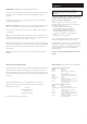
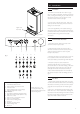
1.0 Warnings 1.1 In an Emergency If a water or gas leak occurs or is suspected, the boiler can be isolated at the inlet valves as follows; 1. Turn off the electrical supply and turn the selector switch on the facia box to the OFF position. Gas Tap 2. Using a suitable open ended spanner or screwdriver turn the square on the gas tap to the left to isolate the gas supply at the boiler (Fig. 1). 3.
2.0 Introduction 2.1 Introduction 1. Your Baxi Combi Instant 80 HE or 105 HE is a gas fired, room sealed, powered flue condensing combination boiler, providing central heating for your home and mains fed domestic hot water to taps and shower. It is fully automatic and does not have a pilot light. 2. Priority is given to the hot water mode - when a hot water tap is turned on the supply of heat to the central heating circuit is interrupted. Hinged Lower Door Panel Facia Panel 3.
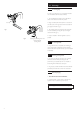
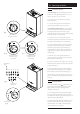
3.0 Operating the Boiler 3.1 Operating the Boiler 1. Ensure that the electricity and gas supplies are turned on. Check that the central heating pressure is between 0.5 and 1.0 bar (Fig. 4). 6 7 o 30 8 o 40 9 o 50 10 o 60 2. Turn the On/Off/Reset selector switch either anticlockwise from the off position (Fig. 6) to both central heating and domestic hot water or clockwise to domestic hot water only. 11 o 70 o 3. In either position the green power on indicator ( ) will illuminate (Fig. 5).
3.0 Operating the Boiler 3.2 Temperature Control 1. Central Heating: The central heating hot water flow temperature can be adjusted between 30° C (± 5° C) minimum and 85° C (± 5° C) maximum. 2. Turn the control knob clockwise to increase the temperature (Fig. 9). 3. In normal winter usage we recommend that the central heating temperature be set at maximum. 4. Domestic Hot Water Pre-Heat: To enjoy optimum performance of the boiler the pre-heat control should be set fully clockwise to the ON position (Fig.
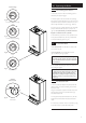
3.0 Operating the Boiler Air Flow Monitor Neon Pump/Low Pressure Neon 3.4 Sensor Fault Neons Safety Thermostat Neon o o 30 40 o 50 o 60 o 70 o 80 Safety Thermostats 1. Your Baxi Combi Instant 80 HE or 105 HE is fitted with additional safety devices, which shut down the boiler in the event of the system, the boiler or the flue overheating. The safety thermostat neon ( ) will light in this instance (Fig. 14). 2.
3.0 Operating the Boiler Pressure Gauge 3.9 Central Heating System Pressure 2 1 3 1. The water pressure in the central heating system is indicated by the pressure gauge. 4 0 bar Fig. 18 Normal Pressure (when cold) 2 3 1 2. With the system cold and the boiler not operating the pressure should be between 0.5 and 1.0 bar. During operation the pressure should not exceed 2.5 bar, and will normally be between 1.0 and 2.0 (Figs. 18 & 19). 3. A pressure of 3 or greater indicates a fault.
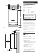
4.0 Clearances and Check List 20mm/5mm Min 450mm 5mm Min see *NOTE: 4.1 200mm Min 1. The minimum clear spaces needed around the boiler measured from the casing are as follows: Top Bottom Left Side Right Side Front 780mm Clearances around the Boiler (Figs. 23 & 24) - 200mm 200mm 5mm 20mm/5mm 5mm (In Operation) 450mm (For Servicing) * NOTE: The boiler can be operated with a clearance of 5mm at the right. This is also sufficient for routine maintenance.
5.0 Cleaning, Spares & Guarantee 5.1 Cleaning the Outercase The painted panels should be wiped with a damp cloth and then dried completely. DO NOT USE ABRASIVE CLEANING AGENTS. 5.2 Spare Parts IMPORTANT - Only a competent person should be used to service or repair this boiler. 1. Any repairs to the boiler will usually be the responsibility of the Installer during the guarantee period after which spare parts may be obtained through approved Baxi stockists if required. 2.
When contacting Baxi Potterton please have the following information to hand: Appliance Name Model Number Serial Number A label giving these details is situated on the rear of the hinged lower door panel attached to the users operating instruction label. Users Operating Instruction Label Lower Door Panel Label B A X I P OTTERTO N 923.611.