
Quick Start Manual
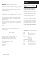
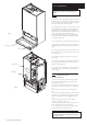


2.0 General Layout
7
© Baxi Heating UK Limited 2005
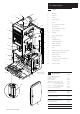
2.1 Layout
1. Wallplate
2. Flue Elbow
3. Air Box
4. Heat Exchanger
5. Burner
6. Fan Protection Thermostat
7. Fan Assembly
8. DHW Plate Heat Exchanger
9. Three Way Valve
10. Facia Box
11. Water Pressure Gauge
12. Gas Tap
13. Circulation Pump
14. Pressure Relief Valve
15. Return Thermistor
16. Gas/Air Ratio Valve
17. PCB
18. Flow Temperature Safety Thermostat
19. Flow Temperature Thermistor
20. Manual Air Vent
21. Automatic Air Vent
22. Flow Switch (Dry Fire Protection)
23. Condensate Trap
24. Expansion Vessel
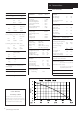
2.2 Optional Extras
KIT PART N
o
FLUE EXTENSION KITS (110/70)
Horizontal Flue Kit 4M max
Flue Extension 0.25M 241692
Flue Extension 0.5M 241694
Flue Extension 1M
(Use two kits for 2M etc.) 241695
Flue Bend - 45°
(Reduce overall length of flue
by 0.5m when fitting this bend)
241689
Flue Bend - 90° (
Reduce overall length of flue
by 1m when fitting this bend)
241687
Horizontal Extended Flue (1.75M) 5111457
VERTICAL FLUE KITS (110/70) 5M max
Vertical Flue Terminal 242802
Vertical Boiler Connection 5106888
VERTICAL FLUE (80/80)
Kit Boiler Connection Twin 242757
CONTROL ACCESSORIES
RF Programmable Room Thermostat 5117204
Electro-Mechanical Timer 5117493
Filling Loop Kit 5111095
Plume Displacement Kit 5117383
1
2
4
5
3
6
7
23
12
16
10
22
13
21
20
14
11
24
8
9
15
Expansion Vessel
removed for clarity
18
19
17