
Operating instructions


Supplied By www.heating spares.co Tel. 0161 620 6677
3.0 System Pressure
6
© Baxi Heating UK Ltd 2011
3.1 Central Heating System Pressure
1. The boiler may be installed in two types of heating
system, ‘sealed’ or ‘semi - sealed’. Your installer will be
able to advise you of the type of system and explain the
operation.
2. The ‘sealed’ type is pressurised from the mains by
means of a device called the filling loop, which may also
be used to re-pressurise the system.
3. The ‘semi - sealed’ type relies on a header tank of
water to fill the system through a non - return valve.
This type of system should automatically maintain
suitable pressure.
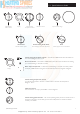
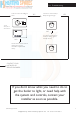
4. The normal operating water pressure must be at least
0.2 bar (Fig. 1) for the boiler to operate. If the pressure
exceeds 3 bar (Fig. 3) the safety pressure valve will
operate and a fault is indicated. Contact your installer.
‘Sealed’ Systems Only
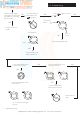
5. It may be necessary to repressurise the system
occasionally (Fig. 2). A filling device (the filling loop) will
be fitted on the system.
6. If you are unsure of its position, or cannot identify it,
consult the installer who fitted the boiler.
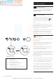
7. The filling loop consists of two taps and a separate
metal braided hose with connection fittings.
8. Only when repressurising should the hose be
connected between the two taps. Ensure that the nuts
on the pipe ends are tightened onto the taps.
9. Fully open one of the taps first, and then while
watching the pressure gauge, carefully open the second
tap.
10. When the needle on the gauge is indicating 0.2 or
more turn both taps off.
11. Disconnect the metal braided hose from the taps (a
small amount of water may be present) and remove it.
Keep the hose in a safe place for future use.
‘Semi - Sealed’ Systems Only
12. The header tank on the ‘semi - sealed’ system should
maintain the pressure at a minimum of 0.2 bar. If the
pressure drops below this consult your installer.
2
1
0
4
3
bar
2
1
0
4
3
bar
Fig. 1
Fig. 2
Normal MINIMUM Pressure
Requires
Repressurising
2
1
0
4
3
bar
Fault
Fig. 3