OWNER’S MANUAL _________________ BAYTECH REMOTE POWER CONTROL UNIT FOR MODELS RPC-2 RPC-2A RPC-2 MD01 RPC-2 RDR RPC-3 RPC-3A RPC-5 BayTech Manual Publication #U140E125-03 July 1998
Copyright 1998 by Bay Technical Associates, Inc. BayTech, Telplex, LaserShare, Print Master and TRAN-X are registered trademarks of Bay Technical Associates, Inc. IBM, IBM PC, IBM PC/AT, IBM PC/XT are products and registered trademarks of International Business Machines Corporation. Hewlett-Packard LaserJet is a product and registered trademark of the Hewlett-Packard Company. PROCOMM PLUS is a product and registered trademark of Datastorm Technologies, Inc.
RPC SERIES OWNER’S MANUAL ABOUT THIS OWNER’S MANUAL ________________________________________________________________________________ ABOUT THIS OWNER’S MANUAL This document provides information required for installing and operating your Bay Tech equipment. It should allow the user to connect, power up, and access an applications menu where peripheral equipment can be controlled. We recommend reading this manual carefully, while placing special emphasis on correct cabling and configuration.
RPC SERIES OWNER’S MANUAL ABOUT THIS OWNER’S MANUAL ________________________________________________________________________________ The information in this document is subject to change without notice. The statements, configurations, technical data, and recommendations in this document are believed to be accurate and reliable, but are presented without express or implied warranty. Users must take full responsibility for their applications of any products specified in this document.
RPC-2 AND RPC-2A QUICK START......................................................................... 2 RPC-2 MD01 AND RPC-2 RDR QUICK START ....................................................... 5 RPC-3, RPC-3A, AND RPC-5 QUICK START .........................
CHANGE OUTLET NAME.............................................................................. 34 RPC-3, RPC-3A, AND RPC-5 .................................................................................... 36 LOCAL ACCESS USING THE EIA-232 PORT ................................................... 37 REMOTE ACCESS USING THE NETWORK PORT .......................................... 37 OPERATION...................................................................................................
# $ ! # $ # $ &" &' # ( vii
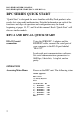
RPC SERIES OWNER’S MANUAL INTRODUCTION TO THE RPC SERIES ________________________________________________________________________________ INTRODUCTION TO THE REMOTE POWER CONTROL SWITCH (RPC) The BayTech RPC-Series is a full-featured AC power management solution that provides an easy way to control power of remote equipment. From your office or from anywhere, the RPC will TURN ON, TURN OFF, OR REBOOT remote equipment. There are six different RPC models. Four models operate at 115 VAC, 15 Amp.
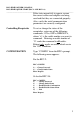
RPC SERIES OWNER’S MANUAL RPC SERIES QUICK START (RPC-2 AND RPC-2A) ________________________________________________________________________________ RPC SERIES QUICK START “Quick Start” is designed for users familiar with BayTech products who need a fast setup and familiarization. Detailed information on each of the functions and steps of operation and configuration may be found beginning at pages 19, 27, and 36 of this manual. Each “Quick Start” will discuss similar models.
RPC SERIES OWNER’S MANUAL RPC SERIES QUICK START (RPC-2 AND RPC-2A) ________________________________________________________________________________ If the status menu fails to appear, ensure the correct cables and adapters are being used and that they are connected properly. Also, verify the serial communication parameters are correctly configured.
RPC SERIES OWNER’S MANUAL RPC SERIES QUICK START (RPC-2 AND RPC-2A) ________________________________________________________________________________ Change Password Default password is . The maximum field length is 8 alphanumeric characters. The password feature is case sensitive. Change Outlet Name Default Outlet Names are Outlet 1, Outlet 2, … The maximum field length is 10 alphanumeric characters. Enable/Disable Confirmation Default setting is enabled.
RPC SERIES OWNER’S MANUAL RPC SERIES QUICK START (RPC-2 MD01 AND RPC-2 RDR) ________________________________________________________________________________ RPC-2 MD01 AND RPC-2 RDR QUICK START Local access using EIA-232 serial connection Using the 9FRJ45PC-1 adapter and the RJ08X007 (8-pin crossed) cable, connect the serial port of your computer to the RJ-45 port labeled “EIA-232.” Load serial port communications software.
RPC SERIES OWNER’S MANUAL RPC SERIES QUICK START (RPC-2 MD01 AND RPC-2 RDR) ________________________________________________________________________________ Using the RJ04X007 (RJ-11) modular cable, connect either port labeled “LINE” on the RPC unit to the telco wall jack. Using another RJ04X007 (RJ-11) modular cable, connect the remaining port labeled “LINE” on the RPC unit to the port labeled “LINE” on the external modem.
RPC SERIES OWNER’S MANUAL RPC SERIES QUICK START (RPC-2 MD01 AND RPC-2 RDR) ________________________________________________________________________________ Controlling Receptacles To set or change the status of the receptacles, enter one of the following commands: ON n, OFF n, REBOOT n, where “n” is the outlet number you want to command. Entering an outlet number of “0” sends the command to all outlets. Reboot only works on outlets which are in the “ON” condition.
RPC SERIES OWNER’S MANUAL RPC SERIES QUICK START (RPC-3, RPC-3A, AND RPC-5) ________________________________________________________________________________ RPC-3, RPC-3A AND RPC-5 QUICK START NOTE: The RPC-3, 3A and 5 are configured in a similar manner. This quick start will reference the RPC-3 menus. The only programming differences for the RPC-5 pertain to the number of receptacles shown in the menus (4 vice 8).
RPC SERIES OWNER’S MANUAL RPC SERIES QUICK START (RPC-3, RPC-3A, AND RPC-5) ________________________________________________________________________________ RPC-3 Telnet Host Revision F 3.03, (C) 1998 Bay Technical Associates Unit ID: RPC3 RPC-3 Menu: 1) . . . Outlet Control 2) . . . Manage Users 3) . . . Configuration 4) . . . Unit Status 5) . . . Reset Unit 6) . . .
RPC SERIES OWNER’S MANUAL RPC SERIES QUICK START (RPC-3, RPC-3A, AND RPC-5) ________________________________________________________________________________ Change Password Default password is ; disabled. Password is case sensitive. Change Outlet List From the User Management Menu, select the number of the user to modify, followed by . Enter the number of the outlet(s) to which you want to give or remove access. If there is more than one outlet, enter the numbers, separated by commas.
RPC SERIES OWNER’S MANUAL RPC SERIES QUICK START (RPC-3, RPC-3A, AND RPC-5) ________________________________________________________________________________ Access Default password is ; disabled. NOTE : If user name and password are disabled (default), outlet users will have access to all admin functions.
RPC SERIES OWNER’S MANUAL INSTALLATION ________________________________________________________________________________ INSTALLATION UNPACKING Compare the unit and serial number of the equipment you received to the packing slip located on the outside of the box. Log this information on the sheet on page 60. Inspect equipment carefully for damage that may have occurred in shipment.
RPC SERIES OWNER’S MANUAL INSTALLATION ________________________________________________________________________________ POWER CAUTION: This unit is intended for indoor use only. Do not install near water or expose this unit to moisture. To prevent heat buildup, do not coil the power cord when in use. Do not use extension cords. Do not attempt to make any internal changes to the power source. Do not attempt to modify any portion or component of an RPC Series Unit unless specifically directed to.
RPC SERIES OWNER’S MANUAL INSTALLATION ________________________________________________________________________________ POWER ON/OFF STATE Each receptacle is individually controlled by an internal relay. Upon initialization of power, the status of each receptacle will return to the state it was in prior to losing power. For example, if Outlet 1 and Outlet 2 are “ON” and power is removed from the RPC, the status of Outlet 1 and Outlet 2 will return to “ON” when power is restored to the RPC.
RPC SERIES OWNER’S MANUAL CABLING ________________________________________________________________________________ CABLING RJ-45 CABLES AND ADAPTERS IMPORTANT: All RPC models have an RJ-45 port for connecting to a local EIA-232 device such as a computer terminal or external modem. Most serial computers do not have RJ-45 connections; therefore, an adapter is provided with this unit to convert from a DE-9 connector to an RJ-45 connector (BayTech Part No. 9FRJ45PC-1).
RPC SERIES OWNER’S MANUAL CABLING ________________________________________________________________________________ The RPC RJ-45 control port uses the following signals: EIA-232 RJ-45 PIN/SIGNAL DEFINITION EIA-232 Signal Direction Description 1 DTR Output +10V when activated by DCD. Toggles on logout for modem disconnect.
RPC SERIES OWNER’S MANUAL CABLING ________________________________________________________________________________ 1 BLUE 2 ORANGE 3 BLACK 4 RJ-45 5 1 DCD 2 RX 3 TX RED 4 DTR 5 GND 6 DSR 7 RTS 8 CTS FEMALE DE-9 GREEN 6 YELLOW 7 BROWN 8 GRAY Figure 5: Computer/Terminal Adapter BayTech Part No. 9FRJ45PC-1 Crossed RJ-45 cable is required Modem Communications: A modem can be connected to the EIA-232 serial port by using a 25MRJ45MD-8 adapter (Figure 6).
RPC SERIES OWNER’S MANUAL CABLING ________________________________________________________________________________ RJ-45 RJ-45 CONDUCTOR PIN PIN 1 1 2 2 COLOR COLOR BLUE BLUE ORANGE ORANGE 3 3 4 4 5 5 6 6 7 7 8 8 BLACK BLACK RED RED GREEN GREEN YELLOW YELLOW BROWN BROWN GRAY GRAY Figure 7: Crossed 8-pin Modular Cable BayTech Part No.
RPC SERIES OWNER’S MANUAL DETAILED OPERATION AND CONFIGURATION ________________________________________________________________________________ DETAILED OPERATION AND CONFIGURATION The following section, “Operation and Configuration,” provides a detailed approach to accessing, operating, and configuring the RPC. NOTE: It is important that you type all commands correctly. Any combination of wrong entries results in an error message. As a result, you will have to start over from the previous menu.
RPC SERIES OWNER’S MANUAL DETAILED OPERATION AND CONFIGURATION ________________________________________________________________________________ Using the 9FRJ45PC-1 adapter (or other applicable adapter) and the RJ08X007 crossed cable, connect the serial port of your computer to the RJ-45 port labeled “EIA232” on the back of your RPC unit. Load serial port communications software. Configure host terminal’s serial communications parameters to match the RPC.
RPC SERIES OWNER’S MANUAL DETAILED OPERATION AND CONFIGURATION ________________________________________________________________________________ Accessing Main Menu Power on the RPC unit. The following status menu appears: RPC-2 Series (c) 1997 by BayTech F2.07 Circuit Breaker : On 1) . . . OUTLET 1 2) . . . OUTLET 2 3) . . . OUTLET 3 4) . . . OUTLET 4 5) . . . OUTLET 5 6) . . .
RPC SERIES OWNER’S MANUAL DETAILED OPERATION AND CONFIGURATION ________________________________________________________________________________ RPC-2 Series (c) 1997 by BayTech F2.07 Circuit Breaker : On 1) . . . OUTLET 1 2) . . . OUTLET 2 3) . . . OUTLET 3 4) . . . OUTLET 4 5) . . . OUTLET 5 6) . . . OUTLET 6 : : : : : : Off Off On Off Off Off RPC > Likewise, typing ON 0 at the RPC > prompt and responding “Y” for yes, turns “On” all outlets.
RPC SERIES OWNER’S MANUAL DETAILED OPERATION AND CONFIGURATION ________________________________________________________________________________ set, the RPC requires password entry before allowing the user to operate the RPC unit. REMEMBER, the password feature is case sensitive. Default outlet names are Outlet 1, Outlet 2, Outlet 3 . . . Outlet 6. From the RPC’s configuration menu, the user can change any outlet name to outline a unique set-up. From the status menu’s RPC > prompt, type CONFIG.
RPC SERIES OWNER’S MANUAL DETAILED OPERATION AND CONFIGURATION ________________________________________________________________________________ typing “CONFIG” to access the configuration menu. If you enter the current password correctly, the RPC responds: Enter New Password: Enter a new password (maximum field length, 8 alphanumeric characters), followed by . The RPC responds: Re-Enter New Password: Re-enter the new password identically to the first entry. The password feature is case sensitive.
RPC SERIES OWNER’S MANUAL DETAILED OPERATION AND CONFIGURATION ________________________________________________________________________________ Enter the number of the outlet you want to change. If you want to change the name of Outlet 4, type the number 4 at the “Enter Request” prompt, followed by . The RPC responds: Enter: Enter a new receptacle name (maximum field length, 10 characters), followed by .
RPC SERIES OWNER’S MANUAL DETAILED OPERATION AND CONFIGURATION ________________________________________________________________________________ From the configuration menu, select #3, “Enable/Disable Confirmation.” Depending on the current status of the switch, the RPC responds with the option to change the current status. Default is Enabled. Disable Confirmation? (Y/N) Enable/Disable Status Menu From the configuration menu, select #4, “Enable/Disable Status Menu.
RPC SERIES OWNER’S MANUAL DETAILED OPERATION AND CONFIGURATION ________________________________________________________________________________ RPC-2 MD01 AND RPC-2 RDR LOCAL ACCESS USING THE EIA-232 SERIAL CONNECTION The RPC-2 MD01 and RPC-2 RDR have an RJ-45 port for connecting to a local EIA-232 device, such as a computer terminal or external modem.
RPC SERIES OWNER’S MANUAL DETAILED OPERATION AND CONFIGURATION ________________________________________________________________________________ parameters are 9600 bps, 8 data bits, 1 stop bit, and no parity. REMOTE ACCESS USING MODEM CONNECTIONS RPC-2 MD01 (Internal Modem) Using the RJ04X007 (RJ-11) modular cable, connect either port labeled “LINE” on the back of the RPC unit to the telco wall jack. RPC-2 RDR (External Modem) Plug the modem’s power supply into receptacle number six on the RPC.
RPC SERIES OWNER’S MANUAL DETAILED OPERATION AND CONFIGURATION ________________________________________________________________________________ OPERATION The RPC’s main menu allows you to monitor and control equipment attached to each of the RPC-2 RDR and RPC-2 MD01’s six receptacles. From this menu, you can turn on, turn off, or reboot attached equipment, individually, or all equipment, simultaneously.
RPC SERIES OWNER’S MANUAL DETAILED OPERATION AND CONFIGURATION ________________________________________________________________________________ If the status menu fails to appear, ensure the correct cables and adapters are being used and that they are connected properly. Also, verify the serial communication parameters are correctly configured.
RPC SERIES OWNER’S MANUAL DETAILED OPERATION AND CONFIGURATION ________________________________________________________________________________ The REBOOT n command will reboot or reset equipment attached to corresponding receptacle(s). When the command to REBOOT (n) is sent from the RPC > prompt, the RPC powers “Off” corresponding outlet(s) for approximately 10 seconds, then powers them up in sequence. This command only works on outlets which were “On” prior to the reboot.
RPC SERIES OWNER’S MANUAL DETAILED OPERATION AND CONFIGURATION ________________________________________________________________________________ RPC-2 Series (C) 1997 by BayTech F2.07 Circuit Breaker : On 1) . . . OUTLET 1 2) . . . OUTLET 2 3) . . . OUTLET 3 4) . . . OUTLET 4 5) . . . OUTLET 5 6) . . . OUTLET 6 : : : : : : Off Off Off Off Off Off IMPORTANT: When operating remotely, do not send the command to turn “off” a receptacle that has a host terminal or modem attached.
RPC SERIES OWNER’S MANUAL DETAILED OPERATION AND CONFIGURATION ________________________________________________________________________________ Change Password From the status menu’s RPC > prompt, type CONFIG. The following menu appears: RPC > CONFIG 1) . . . Change Password 2) . . . Change Outlet Name Enter Request: Select #1, “Change Password,” and press The RPC responds: Enter Current Password: Since the factory default password is a carriage return, press .
RPC SERIES OWNER’S MANUAL DETAILED OPERATION AND CONFIGURATION ________________________________________________________________________________ typing CONFIG” from the RPC > prompt to access the configuration menu. If you reenter the new password correctly, the RPC returns to the main menu again, but you will not get an “Error” message. Circuit Breaker : On 1) . . . OUTLET 1 2) . . . OUTLET 2 3) . . . OUTLET 3 4) . . . OUTLET 4 5) . . . OUTLET 5 6) . . .
RPC SERIES OWNER’S MANUAL DETAILED OPERATION AND CONFIGURATION ________________________________________________________________________________ Select #2, “Change Outlet Name,” and press The RPC responds: 1) . . . OUTLET 1 2) . . . OUTLET 2 3) . . . OUTLET 3 4) . . . OUTLET 4 5) . . . OUTLET 5 6) . . . OUTLET 6 Enter Request: Enter the number of the outlet you want to change. If you want to change the name of Outlet 4, type the number 4 at the “Enter Request” prompt, followed by .
RPC SERIES OWNER’S MANUAL DETAILED OPERATION AND CONFIGURATION ________________________________________________________________________________ RPC-3 AND RPC-3A and RPC-5 NOTE: The RPC-3, RPC-3A and RPC-5 are configured in a similar manner. The RPC-5 has 4 outlets and supports 4 users. The RPC-3/3A has 8 outlets and supports 8 users. These differences are minor and not specifically addressed unless significant to the topic of discussion.
RPC SERIES OWNER’S MANUAL DETAILED OPERATION AND CONFIGURATION ________________________________________________________________________________ LOCAL ACCESS USING EIA-232 SERIAL CONNECTION Load serial port communications software. Configure host terminal’s serial communications parameters to match the RPC. RPC factory serial communications parameters are 9600 bps, 8 data bits, 1 stop bit, and no parity.
RPC SERIES OWNER’S MANUAL DETAILED OPERATION AND CONFIGURATION ________________________________________________________________________________ established via a Telnet session from your workstation. Using a straight 10Base-T cable, connect the Ethernet portion the RPC Series to the network hub. The green LINK LED will illuminate when a satisfactory connection is made to the network. If it does not light, check the 10Base-T cable connection to your network. Also, verify status of the CX LED.
RPC SERIES OWNER’S MANUAL DETAILED OPERATION AND CONFIGURATION ________________________________________________________________________________ In the RPC Series’s main menu, #1 “Outlet Control” and #4 “Unit Status” allow the user to monitor and control the equipment attached to each of the RPC’s eight receptacles. Selection #3 puts the user into the configuration menu for setting network parameters, programming user login access, and outlet configuration.
RPC SERIES OWNER’S MANUAL DETAILED OPERATION AND CONFIGURATION ________________________________________________________________________________ If the main menu fails to appear, ensure the correct cables and adapters are being used and they are properly connected. Also, verify the serial communication parameters are correctly configured. If this is not an initial setup and username and/or password have been enabled, you will be prompted to enter a username and/or password.
RPC SERIES OWNER’S MANUAL DETAILED OPERATION AND CONFIGURATION ________________________________________________________________________________ NOTE: The outlet user sees only those outlets as assigned to him by the admin user. From the RPC > prompt, enter one of the following commands: ON n, OFF n, REBOOT n, where “n” is the outlet number you want to command. Entering an outlet number of “0” sends the command to all outlets. Example: To turn “On” Outlet 3, type ON 3 from the RPC prompt (RPC >).
RPC SERIES OWNER’S MANUAL DETAILED OPERATION AND CONFIGURATION ________________________________________________________________________________ receptacle(s). When the command to REBOOT (n) is sent from the RPC > prompt, the RPC powers “Off” corresponding outlet(s) for approximately 10 seconds, then powers them up in sequence. This command only works on outlets which were “On” prior to the reboot. prior to receiving the reboot command.
RPC SERIES OWNER’S MANUAL DETAILED OPERATION AND CONFIGURATION ________________________________________________________________________________ Add User The “Add user” option is presented any time less than 8 (4 for the RPC-5) optional users are defined. Select #1, “Add user,” from the User Management Menu. The RPC Series responds: Enter username (<= 8 characters) > Enter the name of the user to be added, followed by . NOTE: User name is case sensitive.
RPC SERIES OWNER’S MANUAL DETAILED OPERATION AND CONFIGURATION ________________________________________________________________________________ Change Password IMPORTANT: If enabled, the password function provides independent user access to assigned outlets by entering a user name and/or password. If disabled, neither the user name nor password is required, and every user will have access to all admin functions. NOTE: Password can be enabled or disabled for serial login and network login.
RPC SERIES OWNER’S MANUAL DETAILED OPERATION AND CONFIGURATION ________________________________________________________________________________ When you enter the current password correctly, the RPC responds: Enter new password (<= 8 characters) > Enter a new password (maximum field length, 8 alpha-numeric characters), followed by . The RPC responds with: Confirm by Re-Entering New Password: Re-enter the new password identically to the first entry. The password feature is case sensitive.
RPC SERIES OWNER’S MANUAL DETAILED OPERATION AND CONFIGURATION ________________________________________________________________________________ Change Outlet List The outlet list determines which outlets a particular user can access. From the User Management Menu, enter the number of the user to modify, followed by . Then select #2, “Change Outlet List.” The RPC Series responds: To change outlet access, enter number(s) of outlets. If more than one entry, separate numbers with commas. CR to exit.
RPC SERIES OWNER’S MANUAL DETAILED OPERATION AND CONFIGURATION ________________________________________________________________________________ CONFIGURATION Configuration can be performed by the admin user only via the serial port or the network port. From the RPC Main Menu, select #3, “Configuration.” The following menu appears: Bay Technical Associates RPC-3 Configuration Menu MAC Addr: 00.C0.48.05.53.A2 Unit ID: RPC3 Medium Stat: good Active users: 1 Enter choice from menu, CR to exit 1) . . .
RPC SERIES OWNER’S MANUAL DETAILED OPERATION AND CONFIGURATION ________________________________________________________________________________ address is 0.0.0.0. If you fail to enter the IP Address in dotted decimal form, the RPC responds again: Enter IP address in dotted decimal form: The RPC responds indefinitely with the same request until the IP Address in entered in the correct form. Subnet Mask The Subnet Mask consist of four bytes, each byte ranging from 0 to 255.
RPC SERIES OWNER’S MANUAL DETAILED OPERATION AND CONFIGURATION ________________________________________________________________________________ Enter the Gateway address (Example: 200.4.5.50), followed by . The RPC resumes the configuration menu Default Gateway address is 0.0.0.0.
RPC SERIES OWNER’S MANUAL DETAILED OPERATION AND CONFIGURATION ________________________________________________________________________________ Login setup Toggle option by entering number, CR to exit. Network access: 1)...Prompt for user name: disabled 2)...Prompt for password : disabled Serial Port Access: 3)...Prompt for user name: disabled 4)...Prompt for password : disabled Enter the number that corresponds to the prompt you want to toggle.
RPC SERIES OWNER’S MANUAL DETAILED OPERATION AND CONFIGURATION ________________________________________________________________________________ Outlet Status Display From the Outlet Operation Configuration Menu, select #1, “Outlet Status Display.” Depending on whether outlet status display is currently enabled or disabled, the RPC responds with the option to change the current status.
RPC SERIES OWNER’S MANUAL DETAILED OPERATION AND CONFIGURATION ________________________________________________________________________________ From the Outlet Configuration Menu, select #3, “Outlet Power-up Delay.” The unit responds: To set delay, enter number of outlet, CR to exit Outlet power-up delays (in seconds): 1) . . . Outlet 1 : 0 2) . . . Outlet 2 : 0 3) . . . Outlet 3 : 0 4) . . . Outlet 4 : 0 5) . . . Outlet 5 : 0 6) . . . Outlet 6 : 0 7) . . . Outlet 7 : 0 8) . . .
RPC SERIES OWNER’S MANUAL DETAILED OPERATION AND CONFIGURATION ________________________________________________________________________________ Enter number of outlet to name, CR to exit. 1) . . . OUTLET 1 2) . . . OUTLET 2 3) . . . OUTLET 3 4) . . . OUTLET 4 5) . . . OUTLET 5 6) . . . OUTLET 6 7) . . . OUTLET 7 8) . . . OUTLET 8 Enter Request: Enter the number of the outlet you want to change. If you want to change the name of Outlet 4, type the number 4 at the “Enter Request” prompt, followed by .
RPC SERIES OWNER’S MANUAL DETAILED OPERATION AND CONFIGURATION ________________________________________________________________________________ Display Outlet User From the Outlet Operation Configuration Menu, select #5, “Display Outlet User,” followed by .
RPC SERIES OWNER’S MANUAL DETAILED OPERATION AND CONFIGURATION ________________________________________________________________________________ RPC Unit Status Menu 1) . . . 2) . . . 3) . . . 4) . . . System Network Interface Logged Users Outlet Status Enter selection> System Status System Status provides information about the local memory (available buffers), how many TCP sockets are in use, and the time the unit has been operating since the last unit reset or power up.
RPC SERIES OWNER’S MANUAL DETAILED OPERATION AND CONFIGURATION ________________________________________________________________________________ Network Status: Medium status: good Medium faults: 0 Xmit bufr errs: 0 Available send buffers: 29 Receive queue status: open Logged Users This option shows the number of active sessions. For each session, the name of the account, the type of interface (serial or network) and the status is provided.
RPC SERIES OWNER’S MANUAL DETAILED OPERATION AND CONFIGURATION ________________________________________________________________________________ Outlet Status The following table shows the status of all outlets: Outlet Status Selection Number 1 2 3 4 5 6 7 8 RESET UNIT Outlet Name OUTLET OUTLET OUTLET OUTLET OUTLET OUTLET OUTLET OUTLET Outlet Power Number Status 1 2 3 4 5 6 7 8 1 2 3 4 5 6 7 8 Off Off Off Off Off Off Off Off Reset the unit to load new configuration changes.
RPC SERIES OWNER’S MANUAL DETAILED OPERATION AND CONFIGURATION ________________________________________________________________________________ RPC3 > “n” refers to selection number, as displayed in Outlet Status. LOGOUT : terminate session OFF n : turn off outlet “n”, do all for n = 0 ON n : turn on outlet “n”, do all for n = 0 REBOOT n : cycle power off/on outlet “n”, do all for n =0 RC : display outlet relay control information STATUS : display power status of outlets HELP : display this message.
RPC SERIES OWNER’S MANUAL TECHNICAL SUPPORT ____________________________________________________________ TECHNICAL SUPPORT BayTech has a staff of applications engineers on duty to assist you from 7 a.m. to 6 p.m. (CST or CDT), Monday through Friday. If you have problems installing, setting up, or operating your Bay Tech product, please contact BayTech’s technical support office. For information on all of BayTech’s data communication products, contact our Web Site at the address shown below.
RPC SERIES OWNER’S MANUAL TECHNICAL SUPPORT ____________________________________________________________ EQUIPMENT SETUP RPC Series Unit Model ____________ RPC Series Unit Serial Number ____________ OUTLET 1 OUTLET 2 OUTLET3 MODEL MODEL MODEL SERIAL NUMBER SERIAL NUMBER SERIAL NUMBER USE USE USE OUTLET 4 OUTLET 5 OUTLET 6 MODEL MODEL MODEL SERIAL NUMBER SERIAL NUMBER SERIAL NUMBER USE USE USE OUTLET 7 OUTLET 8 MODEL MODEL SERIAL NUMBER SERIAL NUMBER USE USE Type of adap
RPC SERIES OWNER’S MANUAL REPACKAGING, SHIPPING, AND RETURNING TO THE FACTORY ________________________________________________________________________________ REPACKAGING, SHIPPING AND RETURNING TO THE FACTORY If your Bay Tech unit needs service, upgrade, or repair, return it to BayTech. Before dismantling your equipment or before returning the unit for any reason, always call BayTech. The user should never attempt repairs on this unit.
RPC SERIES OWNER’S MANUAL FCC RADIO FREQUENCY INTERFACE STATEMENT ________________________________________________________________________________ FCC RADIO FREQUENCY INTERFACE STATEMENT This equipment generates, uses and can radiate radio frequency energy and, if not installed and used in accordance with this manual, may cause interference to radio communication.
RPC SERIES OWNER’S MANUAL FCC RADIO FREQUENCY INTERFACE STATEMENT ________________________________________________________________________________ d. If the Telephone Company requests information on connected equipment to their lines, inform them of the following: 1. 2. 3. 4. The telephone number of this unit. The ringer equivalence number (indicated on the label). The USOC jack required: RJ-11 The FCC Registration Number (indicated on the label).
RPC SERIES OWNER’S MANUAL APPENDIX A ________________________________________________________________________________ APPENDIX A SPECIFICATIONS Power Receptacle Circuit Breaker EIA-232 Serial Port Network Interface Protocols Frame Types Modem Interface Modem Connectors Dimensions Weight 64 RPC2 RPC2A RPC-2 RPC-2 RPC-3 MDO RDR 1 RPC3A RPC-5 6 each 115 VAC, 60 Hz, 15 Amp 125 VAC, 15 Amp 6 each 230 VAC, 50 Hz, 10 Amp 230 VAC, 10 Amp, Universal IEC 320 Outlets 8 pin modular connector (RJ-45) 6
RPC SERIES OWNER’S MANUAL APPENDIX A ________________________________________________________________________________ APPENDIX A SPECIFICATIONS (Cont.
RPC-SERIES OWNER’S MANUAL APPENDIX B APPENDIX B MODEM COMMAND SUMMARY U.S. ROBOTIC MODEMS COMMAND INTERPRETATION Fixed Serial Port Rate (default) AT&B1 AT&C1 Normal CD Operations (default) AT&D2 Normal DTR Operations (default) ATS0=1 Auto answer telephone line in 4 or fewer rings ATE0 Modem does not display keyboard commands.
RPC-SERIES OWNER’S MANUAL APPENDIX B APPENDIX B MODEM COMMAND SUMMARY (Cont.
RPC-SERIES OWNER’S MANUAL APPENDIX C APPENDIX C DIAGNOSTIC LED INDICATIONS To detect hardware, cabling, or configuration problems upon initialization of power, the RPC Series go through a diagnostic sequence. To help determine the cause of the problem, the RPC Series have a CX LED located on the front, right side of the unit. Upon initialization of power, refer to the table below for interpretation.
RPC-SERIES OWNER’S MANUAL APPENDIX D APPENDIX D RPC TROUBLESHOOTING GUIDE PROBLEM SYMPTOM CAUSE SOLUTION No Menu Blank Screen Cables Adapters Parameters Ensure correct cables and adapters are being used and are connected properly. Verify serial parameters are correctly configured. Password Doesn’t Work Returns to prompt Caps Lock Password feature is case sensitive. Type password exactly as it was originally entered.
RPC-SERIES OWNER’S MANUAL APPENDIX D APPENDIX D - RPC TROUBLESHOOTING GUIDE (Cont’) PROBLEM SYMPTOM CAUSE SOLUTION Cannot access Outlet Control or Configuration “X” in the menu line for the desired operation Multiple Users Network user overrides serial user. Only 1 user in Outlet Control or Configuration at a time. See logged users, Page 56. Network session locks up No response from unit More than 4 sessions open Terminate 1 or more sessions. See logged Users, Page 56.
RPC-SERIES OWNER’S MANUAL APPENDIX D APPENDIX D - RPC TROUBLESHOOTING GUIDE (Cont’) PROBLEM SYMPTOM PING not echoing request Gets request timeout CAUSE Check network connection Forgot Password Cannot access unit past password prompt Call a BayTech Applications Engineer Cannot configure network parameters No access to network parameters Trying to configure thru network port SOLUTION Access unit thru serial port 71
RPC-SERIES OWNER’S MANUAL APPENDIX E APPENDIX E- DRAWINGS RPC-2 72
RPC-SERIES OWNER’S MANUAL APPENDIX E APPENDIX E- DRAWINGS RPC-2A 73
RPC-SERIES OWNER’S MANUAL APPENDIX E APPENDIX E- DRAWINGS RPC-2 MD01 74
RPC-SERIES OWNER’S MANUAL APPENDIX E APPENDIX E- DRAWINGS RPC-2 RDR 75
RPC-SERIES OWNER’S MANUAL APPENDIX E APPENDIX E- DRAWINGS RPC-3 76
RPC-SERIES OWNER’S MANUAL APPENDIX E APPENDIX E- DRAWINGS RPC-3A 77
RPC-SERIES OWNER’S MANUAL APPENDIX E APPENDIX E- DRAWINGS RPC3/3A/5 ETHERNET BOARD 78
RPC-SERIES OWNER’S MANUAL APPENDIX E APPENDIX E- DRAWINGS RPC-5 79
RPC-SERIES OWNER’S MAP INDEX INDEX A Adapter, 2, 5, 6, 8, 12, 16, 19, 20, 27, 28, 37 Adapters, 59 Applications Engineer, iii Asynchronous, 17 ATDT Commands, 31 C Cable, 18 Cables, 59 Cabling, 15 Circuit Breaker, 2, 6, 14, 21, 29, 70 Communications Software, 2, 5, 8, 20, 27, 29, 31, 37 Computer Adapter, 17 Computer/Terminal Adapter, 16 Configuration, 3, 7, 10, 11, 19, 22, 32 Copyright, ii Current Password, 23, 24, 33, 44 D Default, 4, 7, 10, 23, 26, 32, 33, 47, 48, 49, 51, 52, 66, 67 diagnostic, 68 E EIA
RPC-SERIES OWNER’S MAP INDEX R Reboot, 14, 20, 22, 29, 31, 41 Remote Access, 5, 28, 37 Remote Operations, 38 Repackaging, 61 Reset, 22, 31, 41, 55, 57, 70 Returning, 61 Ring Detect Reset, 1 Shipping, 61 Status Menu, 2, 3, 6, 14, 21, 23, 26, 29, 30, 33, 34, 40, 41 T Technical Support, 59 Telco Wall Jack, 6, 28 Telnet, 9, 38, 39, 57, 64, 70 S Saving, 11 Serial Parameters, 2, 5, 20, 27, 37 Serial Port, 2, 5, 8, 10, 20, 27, 31, 37, 68, 71 U Unpacking, 12 Users Manual, iii 81