OWNER'S MANUAL ________________ BAYTECH M SERIES DAC BASE UNIT, V71 HOST MODULE, AND V50/V73/V74/V75/V76/V8 6/V87 4-PORT SERIAL MODULES BayTech Manual Publication #U140E111-02
Thank you for selecting an M Series Data Acquisition and Control (DAC) unit. The information provided in this Owner's Manual explains the various ways you can operate your M-Series DAC and configure it to your own computer system. We suggest that you read this manual carefully before attempting to install the M-Series DAC and that you place special emphasis on correct cabling and configuration. If you have any problems with your installation, please contact a BayTech applications engineer for assistance.
respective holders.
Your M Series DAC unit can be equipped with an optional internal diagnostic modem (service modem). Please check the packing list to determine whether or not the unit is equipped with a service modem. The M Series service modem is designed to be used on standard device telephone lines. It connects to the telephone line by means of a standard jack (USOC RJ11C or USOC RJ45S). Connection to telephone company provided coin service (central office implemented systems) is prohibited.
If any of your telephone equipment is not operating properly, you should immediately remove it from your telephone line, as it may cause harm to the telephone network. If the telephone company notes a problem, they may temporarily discontinue service. When practical, they will notify you in advance of this disconnection. If advance notice is not feasible, you will be notified as soon as possible.
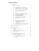
TABLE OF CONTENTS 1 Q U I C K R E F E R E N C E ..................................................................................................... 1 1.1 1.2 G E N E R A L I N F O R M A T I O N .......................................................................... 1 C A B L I N G ....................................................................................................... 2 1.2.1 1.2.2 1.2.3 1.2.4 1.2.5 1.2.6 1.3 2 3 3 3 4 5 C O N F I G U R A T I O N ....................................
5.4 6 B A S E U N I T L E D D E S C R I P T I O N .............................................................. 3 5 B A S E U N I T C O N F I G U R A T I O N ................................................................................ 3 6 6.1 6.2 7 B A S E U N I T F R O N T P A N E L C O N F I G U R A T I O N ...................................... HOST MODULE, SERVICE PORT, AND SERVICE MODEM C O N F I G U R A T I O N ..................................................................................
14.3.1 14.3.2 15 V 8 7 S E R I A L I N T E R F A C E S E L E C T I O N ................................... 8 3 V 8 7 E I A - 4 8 5 C A B L I N G ............................................................ 8 5 V 5 0 / V 7 3 / V 7 4 / V 7 5 / V 7 6 / V 8 6 / V 8 7 O P E R A T I O N................................... 8 5 15.1 V 5 0 / V 7 3 / V 7 4 / V 7 5 / V 76 / V 8 6 / V 8 7 U S E R P R O G R A M M A B L E F E A T U R E S ..................................................................................
16.8 16.9 16.10 16.12 16.13 17 T E R M I N A T E C H A R A C T E R ..................................................................... V50/V73/V74/V75/V76/V86/V87 CHANGE MODE OF O P E R A T I O N ............................................................................................. V 5 0 / V 7 3 / V 7 4 / V 7 5 / V 7 6 / V 8 6 / V 8 7 T I M E T A G M O D E ......................... V50/V73/V74/V75/V76/V86/V87 CONNECT PORT ID ECHO V 5 0 / V 7 3 / V 7 4 / V 7 5 / V 7 6 / V 8 6 / V 8 7 E X I T ......
1 QUICK REFERENCE 1.1 GENERAL INFORMATION This section is intended to provide quick and easy reference to the cabling requirements, configuration, operation and supported commands of the BayTech M Series Data Acquisition and Control (DAC) models. This section describes operation from a V71 host communications module. The BayTech M Series Data Acquisition and Control (DAC) models are versatile multifunction units used in data collection and process control.
8 channel 12 bit A/D converter, 8 channel control relay, 16 channel switch or optically isolated inputs, 4 EIA-232 serial I/O ports, 4 EIA-232/422 I/O ports, 4 EIA-485/422 I/O ports, 4 current loop ports, 16 MB memory module and a programmable control module.
1.2 CABLING 1.2.1 SERVICE PORT The service port has an RJ-45 modular connector. An adapter is required to connect an IBM PC to the service port. Figure 1 shows the required adapter for a PC with a DB-25 connector and Figure 2 shows the required adapter for a PC with a DE-9 connector. Use a crossed RJ-45 cable to connect these adapters to the service port.
1.2.2 V71 HOST COMMUNICATIONS MODULE The V71 has a DB-25 male DTE connector and an RJ-45 connector for interface to the host device. The default setting provides EIA-232 communication on the DB-25 port and the EIA-232 RJ-45 port. In order to connect a DTE device such as a terminal to the V71 DB-25 port, use a crossed or null modem cable as shown in Figure 3 below. See Section 9 for more V71 cabling information.
1.2.3 V74 FOUR PORT EIA-232 SERIAL I/O MODULE Ports on the V74 I/O module have RJ-45 connectors. Most computers, printers, plotters, and modems do not have modular connectors. Therefore, adapters are required to convert DB-25 or DE-9 connectors to modular connectors. Please refer to Section 14 for the required adapter(s). 1.2.4 V77 ADM-1 ANALOG-TO-DIGITAL CONVERTER MODULE The V77 ADM-1 has a DB-25 female connector and allows for 16 single-ended inputs or 8 differential inputs.
Input Pin # Input Ground Ground Channel 8 Channel 7 Channel 6 Channel 5 Channel 4 Channel 3 Channel 2 Channel 1 Ground Ground Ground 1 14 Ground 2 15 Channel 16 3 16 Channel 15 4 17 Channel 14 5 18 Channel 13 6 19 Channel 12 7 20 Channel 11 8 21 Channel 10 9 22 Channel 9 10 23 Ground 11 24 Ground 12 25 Ground 13 Figure 4: Single-ended Input Connections DI Channel # 1 2 3 4 5 6 7 8 Pin # 10 & 22 9 & 21 8 & 20 7 & 19 6 & 18 5 & 17 4 & 16 3 & 15 + Polarity Figure 5: Differential Input Connections 1.2.
Figure 6: Relay Contact Connections 7
1.2.6 V79 PDI-1 SWITCH INPUT AND V80 PDI-2 OPTICALLY ISOLATED MODULES The V79 PDI-1 and V80 PDI-2 modules each have a DC37F connector. Equipment connections for each module is similar. Each input of the V79 module has a ground connection and each input of the V80 module has a return connection. Figure 7 and Figure 8 below show the V79 and V80 connections respectively.
or a host module. The I/O modules are typically programmed from a host module using a menu-driven procedure as described in this section or by downloading specific configuration commands. I/O modules can be programmed using menus from the service port.
1.3.1 HOST MODULE CONFIGURATION PROCEDURE To access configuration mode of the M Series System from the V71 host module, use the following procedure: 1. Connect a terminal to the host module and configure the terminal's serial parameters to match those of the V71 host module. From the factory, the V71 host module is set at 9600 baud rate, 8 word size, 1 stop bit, and no parity. 2.
2. Connect to the desired module or the main unit by sending $BTn, ($BAYTECHn on M4 and M8) the desired module number (1 to 16 or 0 for the main unit), and Carriage Return or Line Feed.
3. Access configuration mode by sending $CONFIG. Following the example on the previous page, you would send $BT1$CONFIG to configure Module 1. Use $BAYTECH1$CONFIG on M4 and M8 units. 1.3.3 MAIN UNIT CONFIGURATION You can program the date, time, and unit number on the main unit. The date and time are used for event recording and initiation.
X) Exit Configuration Enter Request : 13
1.3.5 V77 ADM-1 CONFIGURATION You can program the sampling setup, reporting setup, channel input setup, and enable dynamic configuration for the V77 ADM-1 analog-to-digital module. If you access configuration mode for the V77 ADM-1, you will receive the following menu: Copyright (c) Bay Technical Associates, 199X DAC V77 ADM-1 Rev. 1.00 This Module is X Module Status..................1 Sampling Setup.................2 Reporting Setup................3 Channel Input Setup............4 Dynamic Configuration.
of Samples to Average is the number of samples averaged per data message.
REPORTING SETUP By entering "3" (Reporting Setup) from the ADM-1 main menu shown on the previous page, the following menu will be displayed: Reporting Method..................1 Report Start Time.................2 Report Interval...................3 Set Host Address..................4 Data Format.......................5 Time Tag..........................6 Terminating Character(s)..........7 Exit..............................
17
Range and Unipolar/Bipolar are used to choose one of eight different voltage ranges. These are 0 to +10 volts, -5 to +5 volts, 0 to +5 volts, -2.5 to +2.5 volts, 0 to +2.5, -1.25 to +1.25 volts, or 0 to +1.25 volts, -0.625 to +0.625 volts. You can select a ninth voltage range which is -10 to +10 volts by installing JP1. Single Ended/Differential setting is used to select up to 16 single-ended channels or up to 8 differential channels.
Relay Operating Setup...........2 Reporting Setup.................3 Dynamic Configuration...........4 Exit............................
NOTE: Reporting Setup is the same as described for the ADM-1 on Page 9. Dynamic Configuration is enabled or disabled the same as described for the ADM1 on the previous page. RELAY OPERATING SETUP By entering "2" (Relay Operating Setup), the following menu will be displayed: List Current Schedule..............1 Create/Modify Schedule.............2 Enable/Disable Events..............3 Delete Schedule....................4 Exit...............................
Module Status...................1 Sampling Setup..................2 Reporting Setup.................3 Dynamic Configuration...........4 Exit............................
NOTE: Reporting Setup is the same as described for the ADM-1 on Page 9. Dynamic Configuration is enabled or disabled the same as described for the ADM1 on the previous page. SAMPLING SETUP By entering "2" (Sampling Setup), the following menu will be displayed: Debounce Delay..................1 Latch Polarity..................2 Exit............................
Mode of Operation...........................7 Time Tag Mode...............................8 Connect Port ID Echo........................9 Port EIA Driver.............................A Exit........................................
Serial Port Configuration allows you to program the baud rate, word size, stop bits, parity and XON/XOFF handshaking for each individual port of the V74 module. Port Device Name allows individual logical names to be assigned to each port for reference while is in configuration mode. Port I.D. formats the port identification code that precedes messages. Designate Host Module Location is used to assign which host module will receive messages while the V74 is operating in immediate reporting mode.
sequence to the host module. The select sequence consists of the port select code (default = $BT), the desired module number (1 to 16), and a terminating character of Carriage Return (0D Hex) or Line Feed (0A Hex). Once an I/O module is selected, you can send commands which are summarized in the following sections.
messages until another Calibrate command is issued. CBc (c=Ch# 1 to 16, 0=all*) Clear Buffer. Clears all old data from the buffer when a new data set is started. RA c (c=Ch# 1 to 16, 0=all*) Report All Buffered Samples. RSc (c=Ch# 1 to 16, 0=all*) Report Single Sample if Available SAc (c=Ch# 1 to 16, 0=all)* Sample and report a sample at the programmed Sampling Setup. * Multiple channels are selected using 4 formats.
(SPDT) relays. Each relay has a set of normally open (NO) and a set of normally closed (NC) contacts capable of switching AC and DC loads up to 3 amps. All relays on the V78 CRM-1 are programmable to change state on demand by sending commands or via time schedule. The status of individual relays is presented as a "1" if the relay is energized or "0" if the relay is de-energized.
The table below summarizes the commands supported by the CRM-1. Please see the V78 CRM-1 operator's manual for a more detailed operational description of the supported commands. V78 CRM-1 COMMAND SUMMARY Command Description CBr (r=Relay# 1 to 8, 0=all*) Clear Buffer. Clears all buffered relay status history (change of state).
29
1.4.4 V79 PDI-1 AND V80 PDI-2 COMMANDS AND DATA PRESENTATION The PDI-1 and PDI-2 have sixteen input channels capable of sensing, recording, and reporting information from dry contact closures (PDI-1) or optically isolated inputs (PDI-2). A module can observe, record, and report when an event happened, how long the event lasted, and how many events occurred. An event is defined as a change-in-state of an input from LO to HI (or vice versa) and return to the original state.
is selected, a message is reported at the start of an event. If Schedule Reporting Method is selected, events are buffered and reported at specific user-selected times or intervals.
The following example shows messages received using immediate or schedule reporting where the PDI-1 or PDI-2 is installed in Unit 1 Module 15 with Time Tagging enabled: 1:15,1 1 11/18/97 09:12:22 1:15,2 1 11/18/97 09:12:22 where 1:15,1 represents Unit 1/Module 15/Channel 1, 1:15,2 represents Unit 1/Module 15/Channel 2, 1 indicates that Channel #1 and Channel #2 are closed, 11/18/97 09:12:22 is the time tag which is the same for both channels in this example, and is the Carriage Retu
If you issue the RS1 command (Report Single Buffered Event), the module responds with a message showing the input status for Channel 1 similar to the following: 1:15,1 1 11/18/97 09:12:22 where 1:15,1 represents Unit 1/Module 15/Channel 1, 1 indicates the first buffered sample for Channel 1 is closed, and 11/18/97 09:12:22 is the time tag. The table below summarizes the commands supported by the PDI-1 and PDI-2.
1.4.5 V74 EIA-232 SERIAL MODULE OPERATION The V74 4-port EIA-232 serial module will simultaneously multiplex incoming data from connected peripheral devices (e.g., bar code readers, digital laboratory instruments, etc.). The V74 allows the host computer to individually select any peripheral device and send data to the selected device. The V74 has four modes of operation. Full duplex reporting mode provides full duplex communication between the host computer and a selected peripheral device.
Command reporting mode allows the host computer to send commands requesting messages or any buffered data from the V74 ports. These commands are summarized in the table on the following page. See Section 1.4.1 for the procedure to send commands. As an example, suppose the V74 is installed in Unit 1 Module 15 and is using Command Reporting Method.
reports all messages in the buffer at the time the command was sent. If there are no messages, is sent to the host controller. RBn (n=1 to 4, 0=all) Report All Buffered Data. This command reports all data in the buffer at the time which the command was received with no regard for messages. If there is no data, is sent to the host controller. RSn (n=1 to 4, 0=all) Report Single Message. This command reports a single buffered message.
The I/O modules are used to interface directly to various peripheral devices such as security/alarm systems, process control systems, medical data systems, and environmental control systems. The I/O module types include a 16 or 8 channel 12 bit A/D converter, 8 channel control relay, 16 channel switch or optically isolated inputs, 4 EIA-232/422 serial I/O ports, and 4 EIA485/422 serial I/O ports. NOTE: This section describes the functionality of the base unit only.
3 BASE UNIT SPECIFICATIONS I/O MODULES: A maximum of sixteen modules can be installed in the M16, nine in the M9, eight in the M8, six in the M6, four in the M4, and three in the M3. POWER REQUIREMENT: M16: 115 VAC, 60 Hz, .5A; or 230 VAC, 50 Hz, .25A M9: 115 VAC, 60 Hz, .3A; or 230 VAC, 50 Hz, .2A M8: 115 VAC, 60 Hz, 0.3A; or 230 VAC, 50 Hz, 0.175A M6, M4, and M3: AC Adapter Input: 115 VAC, 60 Hz, 15 watts maximum; Output: 14-16 VAC, .8A POWER SUPPLY: +5VDC, 0.3A; +12VDC, 0.2A; -12VDC, 0.2A.
95% humidity.
DIMENSIONS: M16 - 16:"w x 10"d x 53"h. M9 - 16:"w x 10"d x 32"h. M8 - 93"w x 10"d x 53"h. M6 - 16:"w x 10"d x 2e"h. M4 - 75 / 1 6 "w x 83/8 "d x 41 / 1 6 "h M3 - 16:"w x 10"d x 1:"h WEIGHT: M16 - 16 lbs with 16 modules installed. 11 lbs with no modules installed. M9 - 14 lbs with 9 modules installed. 8 lbs with no modules installed. M8 - 11 lbs with 8 modules installed. 7 lbs with no modules installed. M6 - 8 lbs with 6 modules installed. 6 lbs with no modules installed. M4 - 7 lbs with 4 modules installed.
WARRANTY: One year on parts and labor.
FACTORY POWER-UP DEFAULT CONFIGURATIONS Time-of-Day Clock Day of the week: 1 (Sunday) Year: 93 (1993) Month: 10 (October) Day: 6 Minutes: 09 Seconds: 00 Unit Number: 1 USER-PROGRAMMABLE CONFIGURATIONS Easy to configure using on-screen menus from the service port, service modem, host module, or control panel. Choices are saved in non-volatile memory to become the new power-up default configuration.
4 BASE UNIT INSTALLATION 4.1 UNPACKING After opening the box, check the packing list that comes with the M Series to ensure that you have received all components. At a minimum you should have received the unit, this manual with any applicable addendums and separate manuals for the I/O modules, and a software utility diskette. The M3, M4, M6 and M9 are provided with an external AC power adapter. Check the unit to make certain that it did not incur damage during shipping.
diskette into your PC's disk drive and then enter the command TYPE README.RDM from your disk drive prompt. To print this file, enter the command COPY README LPT1: from your disk drive prompt.
4.3 POWER The M16 DAC and M8 DAC require 115 VAC, 60 Hz power and come with a three-prong power cord. Do not attempt to operate the unit with a two-prong socket or adapter. 230 VAC, 50 Hz is optional. Plug the AC connector into an AC outlet. The M9, M6, M4, and M3 require external AC power. Plug the AC jack of the external power supply into the receptacle on the back of the unit. Plug the AC connector into an AC outlet.
locations. Never touch uninsulated telephone wires or terminals unless the telephone line has been disconnected at the network interface.
The service port has an RJ-45 modular connector. Most serial computers and terminals do not have modular connectors. Therefore, adapters are required to convert from DB-25 or DE-9 connectors to modular connectors. The service port uses the following communication signals: SERVICE PORT 8-PIN MODULAR EIA-232 PIN/SIGNAL DEFINITION PIN SIGNA L DIRECTIO N DESCRIPTION 1 DTR Output Data Terminal Ready. Enable/disable receiving characters 2 DCD Output Data Carrier Detect.
48
Figure 11 shows the required cable to connect the adapters to the service port.
4.5 MODULE INSTALLATION Some of the modules that can be installed in the M Series include the following: Part No. Description Connector Type V50 I/0 module: 4 EIA-232 serial ports, isolated interface RJ-45 V71 Host module: EIA-232/EIA-422/current loop interface DB-25 & RJ45 V72 & V72TP Host module: Ethernet (IEEE 802.
* - The M03 memory module occupies one module slot thereby reducing the maximum number of host or I/O modules the can be installed by one VERY IMPORTANT!!!: The first module slot (Module 1) of a M8 or M16 with a LCD display must be occupied by a host module.
You will need a straight-slot screwdriver to perform the installation. 1. IMPORTANT: Remove power from the unit by depressing the power switch on the front of the unit to OFF and also remove the power cord from the socket. 2. Determine which module slot the module will install into. Modules are typically installed in sequence from left to right (facing rear of unit). The module slots are labeled on the top panel as "1", "2", ..., "16".
6. Apply power to the unit by plugging in the power cord and depressing the power switch on the front of the unit to ON.
5 BASE UNIT OPERATION 5.1 BASE UNIT USER-PROGRAMMABLE FEATURES You can program the year, month, day, hours, minute, and second for the main unit. All modules derive their time from the base unit's time-of-day clock. You can also program the Unit Number from 1 to 30. 5.2 BASE UNIT BASIC OPERATION The M Series base unit acts as a switch between the host control module(s) and the I/O modules.
55
Bay Technical Associates Data Acquisition Controller Bay Technical Assoc. Select Module 00 NOTE: Only modules actually installed appear in the first screen on the previous page. If a module slot is empty, a blank is shown. This example shows sixteen modules installed. Once all module LEDs are out or the "Bay Technical Assoc." menu is displayed on the LCD, the unit is in operations mode and ready to accept commands and/or data.
57
5.3.1 BASE UNIT READ TIME (RT) COMMAND The Read Time (RT) command is used to obtain the current time and date from the base unit's time-of-day clock. A user connected to a V71 host module or a user connected to the service port or service modem can issue the Read Time command. The user must select the base unit prior to sending the Read Time command. A user connected to a V71 host module selects the base unit by sending the port select code, "0", and Carriage Return or Line Feed.
the default values. 5.3.3 ECHO MODE The service modem can be set to an "echo" mode by sending seven semicolons(;) in succession from the host terminal. While in echo mode, ther service modem will echo back all characters received by the connected terminal. Echo mode is terminated by selecting a specific M-Series module ($BTm m= 1-16) or a specific peripheral communications port ($BTm,p M = 1 to 16 and p = 1 to 4. 5.
module selects Port 1 of a V74 module, the LED for Port 1 of the V71 module and Port 1 of the V74 module will illuminate. If a V71 host module places a V74 module into configuration mode, all LEDs for the V74 module and Port 1 of the V71 host module will illuminate. Units equipped with LEDs have two LEDs for the service modem and a single LED for the EIA-232 service port.
6.1 BASE UNIT FRONT PANEL CONFIGURATION NOTE: This section does not apply to units equipped with LEDs. The base unit is configured from the front panel by pressing the SELECT key when the LCD displays "Module 0 /0 / ". The base unit main menu will appear as follows: MAIN MENU Set Time Set Date Set Unit You can select the current time and date as well as the Unit Number from this menu.
NOTE: While in configuration mode, the time-of-day clock is not updated until the "SET TIME" menu is exited. The time reported by individual modules may not be updated immediately. Modules are operating properly if they update their reporting times within a minute from the time the "SET TIME" menu is exited.
If you select "Set Date" from the "MAIN MENU", the following menu will appear: SET DATE MM/DD/YY Up and Dwn to change Select to accept The "SET DATE" menu is used to program the base unit's date. The first highlighted entry is year (YY). Choose the desired year using the > and ? keys and press SELECT. The next highlighted entry is day (DD). Likewise, use the > and ? keys to select the desired minutes and press SELECT. The last highlighted entry is month (MM).
6.2 HOST MODULE, SERVICE PORT, AND SERVICE MODEM CONFIGURATION To access configuration mode of the base unit from the V71 host module, use the following procedure. The MSeries service port and the V71 host module will not respond to commands for approximately 15 seconds after the unit is powered up or reset. 1. Connect a terminal to the V71 host module and configure the terminal's serial parameters to match those of the host module.
the terminal's serial parameters to 9600 baud rate, 8 word size, 1 stop bit, and no parity. If configuring from the service modem, establish a connection between the remote terminal and service modem by dialing into the service modem. Once the unit is powered on, the following message will be sent out of the service port: Bay Technical Associates Service Port Firmware Revision 4.XX This same message will be sent to the remote modem once a connection is established with the service modem.
The service modem has priority over the EIA-232 service port. When a connection is established between a remote modem and the service modem, the following message will be sent out of the EIA232 service port: Incoming call Service port access locked out A terminal connected to the EIA-232 service port is not allowed access to the M Series unit while the service modem has a connection with a remote modem.
Set Date......................1 Set Time......................2 Set Unit Number...............3 Exit System Menu..............
Enter the desired selection. The "X" selection (Exit System Menu) will return you to operations mode. Once you exit configuration mode, you should disconnect by sending $BT if configuring from the V71 host module or $BT if configuring from the service port or service modem. (Use $BAYTECH when using M4 and M8 DAC). SET DATE If you type "1" from the menu above (Set Date), you will receive the following menu: Enter date : Type the desired date.
6.3 BASE UNIT DYNAMIC CONFIGURATION COMMANDS You can configure the date and time for the base unit from a host communications module by sending the "ST" (Set Time) dynamic configuration command. The host communications module must first select base unit prior to sending the "ST" command. This is done by sending the port select code, "0", and Carriage Return or Line Feed.
7 V71 GENERAL INFORMATION The V71 Host Communication Module is the primary user interface to the BayTech M Series Data Acquisition and Control (DAC) units. This module allows a connected host terminal to issue specific configuration or data commands to the various I/O modules or the M Series unit main board. Multiple V71 modules can be installed in an M Series chassis allowing certain I/O module types to send data to specific V71 modules.
8 V71 SPECIFICATIONS INTERFACE: Asynchronous; EIA-232, -12v mark, +12v space; EIA-422 0 to +5 volt differential (TX+, TX-, RX+, RX-); current loop. CONNECTORS: DB-25 or RJ-45. HANDSHAKING: CTS/DTR or selectable XON/XOFF. DIMENSIONS: 6"h x 4.5"w. FACTORY POWER-UP DEFAULT CONFIGURATIONS: Baud rate: 9600. Word size: 8 bits. Parity: None. Stop bits: 1. XON/XOFF: Disabled. Port Select Code: $BT Line Interface: EIA-232 USER-PROGRAMMABLE CONFIGURATIONS: Easy to configure using on-screen menu or front panel.
Line Interface: EIA-232, EIA-422, or current loop. Port Select Code: Any ASCII character string up to 8 characters.
9 V71 CABLING The V71 has a DB-25 and two RJ-45 connectors for interface to the host terminal. The V71 supports three line interfaces: EIA-232, EIA-422, and current loop. The factory default setting provides EIA-232 line interface on the DB-25 port and the EIA-232 RJ-45 port. The line interface is programmed by entering into the V71 configuration mode (see Section 11).
9.1 V71 EIA-232 LINE INTERFACE See Section 9.1.1 if using DB-25 cabling (default) or Section 9.1.2 if using RJ-45 cabling. 9.1.1 V71 DB-25 CABLING FOR EIA-232 The DB-25 port on the V71 has a male DTE type connector and uses the following pins and signals for communication: DB-25 PIN/SIGNAL DEFINITION FOR EIA-232 LINE INFORMATION Pin# EIA232 Signal Direction Description 1 PGND ---- Protective Ground 2 TX Output 3 RX Input 4 RTS Output + 12 volts when the M16/M8 DAC is powered up.
V71 - DTE FEMALE DB-25 DCE DEVICE MALE DB-25 V71 - DTE FEMALE DB-25 DTE DEVICE FEMALE DB-25 75
76
9.1.2 V71 RJ-45 CABLING FOR EIA-232 The V71 provides EIA-232 line interface on the EIA-232 RJ-45 modular port. Most serial computers, modems, and printers do not have RJ-45 modular connectors. Adapters are required to convert from DB-25 or DE-9 connectors to modular connectors. BayTech has a complete line of RJ-45 adapters and cables that make your installation quick and trouble free. Figure 14 and Figure 15 are drawings of a RJ-45 receptacle and plug. The pin number assignments are given.
characters 78
COMPUTER INTERFACE To interface a computer or terminal to the V71, refer to the RJ-45 adapter drawings below. Refer to Figure 16 below if host computer or terminal has a DB-25 male connector (most IBM XT and PS/2 type computers). Refer to Figure 17 if the host computer has a DE-9 male connector (IBM AT type computers).
MODEM INTERFACE To interface your asynchronous modem to the V71 refer to Figure 18. IMPORTANT: When modular connectors are used as shown in Figures 16 - 18 above, crossed RJ-45 cables are required. See the cable diagram below.
9.2 V71 EIA-422 LINE INTERFACE See Section 9.2.1 if using RJ-45 cabling (default) or Section 9.2.2 if using DB-25 cabling. NOTE: When using EIA-422 line interface, you must access configuration mode and reconfigure the line interface to EIA-422 as described in Section 11.4. 9.2.
connected to HSI (and vice versa), and have the signal grounds connected. Please see Figure 20 on the following page.
V71 (EIA-422, 8-wire) RJ-45 Equipment Connections 1 2 3 4 5 6 7 8 HSI GND RX+ RXTXTX+ GND HSO HSO GND TX+ TXRXRX+ GND HSI Figure 20: V71 RJ-45 (8-wire) Connection for EIA-422 Line Interface NOTE: If you wish to use RJ-11 (4-wire) cabling, connect pins 3 through 6 on the RJ-45 connector as shown in Figure 20. In addition, you should enable XON/XOFF handshaking as described Section 11.4. 9.2.
16 RX+ Input 20 HSO Output 84 Receive Data (+) Handshake Out, enable/disable the receiving of characters
The required cable should have TX+ connected to RX+ (and vice versa), TX- connected to RX- (and vice versa), HSO connected to HSI (and vice versa), and have the signal grounds connected. Please see Figure 21 below. V71 (EIA-422) DB-25 1 GND 2 TX3 RX5 HSI 7 GND 14 TX+ 16 RX+ 20 HSO Equipment Connections GND RXTXHSO GND RX+ TX+ HSI Figure 21: V71 DB-25 Connection for EIA-422 Line Interface NOTE: If you wish to use 4-wire cabling, connect pins 2, 3, 14, and 16 on the DB-25 connector as shown in Figure 21.
25 86 RX- Input Receive Data (-)
The V71 RJ-45 port uses the following signals for current loop line interface with active transmit and active receive: DB-25 PIN/SIGNAL DEFINITION FOR CURRENT LOOP (ACTIVE TX ACTIVE RX) Pin# Current Loop Signal Direction Description 7 GND ---- 9 TX+ Output Transmit Data (+) 11 T X- Output Transmit Data (-) 18 RX- Input Receive Data (-) 19 RX+ Input Receive Data (+) 25 GND ---- Ground Ground Figure 22 below shows the basic active transmit circuit, Figure 23 shows the basic passive
88
Figure 25 below shows the recommended cable to connect the host computer to the V71 with active transmit and passive receive. V71 (Current Loop) DB-25 Equipment Connections 9 TX+ 11 TX- RX+ RX- 18 RX+ 25 RX- TX+ TX- Figure 25: Recommended Cabling Using Current Loop Line Interface (Active Transmit Passive Receive) Figure 26 below shows the recommended cable to connect the host computer to the V71 with active transmit and active receive.
10 V71 OPERATION Section 10.1 discusses user-programmable operations and Section 10.2 discusses basic V71 operation. 10.1 V71 USER-PROGRAMMABLE FEATURES User-programmable features for the V71 include the port select code and serial port configuration. These features are programmed by accessing the menu-driven configuration mode from the V71 or service port (see Section 11).
each individual port. In addition, you can select the line interface for the V71. Section 8 (V71 Specifications) lists the possible values for these features. The factory default serial port configuration is 9600 baud rate, 8 bit word size, 1 stop bit, no parity, XON/XOFF handshaking disabled, and EIA-232 line interface.
10.1.3 V71 RESET COMMAND The entire M-Series unit can be reset by issuing a reset command to the V71. The reset command consists of the port select code ($BT - default) followed by "RESET" and a terminating character of Carriage Return or Line Feed. For example, if using the default port select code, send $BTRESET to the V71 to reset the unit, where is Carriage Return. 10.1.
Configuration is done via verbose (menu-driven) mode or non-verbose mode where a character string is sent to configure the desired I/O module. You can also configure the system clock of the M Series unit from the V71 in the verbose mode. The supported configuration and data commands for a specific I/O module are described in the documentation for that module. All I/O modules can be programmed to communicate in immediate reporting mode where data is sent to the host computer as it is received.
message. You will have to wait until the other host module or service port disconnects from the desired I/O module or main board. If you attempt to connect to a module from the service port and the module is currently in command mode, you will receive the following message: Requested Module is Busy!. 11 V71 CONFIGURATION Configuration changes for the V71 module are made from the host terminal, the service port, or the front panel of a M8 or M16 with LCD.
configuration mode. IMPORTANT: No characters should be typed between $BT1 and $CONFIG. If this happens, the entire configuration sequence is discarded and you will have to send the configuration sequence again. NOTE: The procedure to access configuration mode for the V71 from the service port is the same as described above except you connect your terminal to the service port which has a fixed serial configuration of 9600 bps, 8 bit word size, 1 stop bit, and no parity.
position. 11.2 V71 STATUS By responding to the Enter Request: message at the end of the main configuration menu (see Section 11.1) with "1" (Status), you can review the current configuration of the V71.
Type the desired port select code followed by . For example, if you type #PORT followed by , the V71 will respond with: Port Select Code is:#PORT Enter Port Select Code (Max. 8 Characters) and ENTER when done: If no additional change is desired, type . The V71 saves the new port select code permanently in the non-volatile memory and return to the main configuration menu (see Section 11.1). NOTE: You cannot program the port select code to be $BAYTECH from the service port.
11.4 V71 SERIAL PORT CONFIGURATION By responding to the Enter Request: message at the end of the main configuration menu (see Section 11.1) with "3" (Set Serial Port Configuration), you can change the serial configuration for V71 (i.e., baud rate, word size, stop bits, parity, and XON/XOFF handshaking, and line interface).
Send "G" for 115.
--------------------------------------------------------------| Port | Baud | Word | Stop |Parity| Xon / Xoff | Line | | | Rate | Size | Bits | | Xmit | Recv | Interface | --------------------------------------------------------------| 1 |115200 | 8 | 1 |None | Off | Off | EIA-232 | --------------------------------------------------------------Exit/Save......1 Set Stop Bits..4 Set Line Interface..7 Set Baud Rate..2 Set Parity.....5 Set Word Size..3 Set XON/XOFF...
11.5 V71 EXIT CONFIGURATION By responding to the Enter Request: message at the end of the main configuration menu (see Section 11.1) with "X" (Exit Configuration), the V71 exits configuration mode and return to operations mode. If you happen to make any changes to the serial port configuration, the V71 will respond with: Change your devices to match new configuration This reminds you to change the host computer to match any serial port configuration changes.
11.6 V71 CONTROL PANEL CONFIGURATION You can review the current status and program the serial port configuration for the V71 from the control panel of an M4 with LCD, M8, or M16. To access configuration mode for the V71 from the control panel, highlight the appropriate module number using the arrow keys and the press the SELECT key.
12 V50/V73/V74/V75/V76/V86/V87 GENERAL INFORMATION The V50, V73, V74, V75, V76, V86 and V87 I/O modules are used in conjunction with a host module. The V74 has four EIA-232 serial ports, the V75 has four selectable EIA-232/EIA-422 serial ports, the V76 has four current loop ports, and the V86 and V87 have four selectable EIA-422/EIA-485 serial ports. The V50 has 4 isolated EIA-232 ports and the V73 has 4 EIA-232 ports where the voltage signals are TTL levels.
Immediate Data Mode - Immediate data mode is similar to immediate message mode. The primary difference is that immediate data mode does not wait for a message terminating character to send data to the designated host module. Data is sent to the designated host module automatically as soon as it is received by any port on the peripheral communications module. Command Mode - Reports a single message, all messages, or all buffered data from specific peripheral devices upon request from the host computer.
Port ID: UU:MM,PP - enabled; UU = Unit Number, MM = Module Number, and PP = Port Number. Designate Host Module Location: Unit 1, Module 1, Port 1 Message Terminating Character: Carriage Return (0D Hex). Mode of operation: Full duplex mode. Time Tag: Disabled. Connect Port ID Echo: Disabled Port EIA Driver: Current EIA line driver is : RS485 USER-PROGRAMMABLE CONFIGURATIONS: Baud rate*: 300, 600, 1200, 2400, 4800, 9600, 19.2k, 38.4k, 76.8k, and 115.2k bps. Other rates optional.
INTERFACE: Asynchronous EIA-232, -12v mark, +12v space (V74 and V75); EIA-422 0 to +5 volt differential TX+, TX-, RX+, RX- (V75, V86 & V87); 20 mA current loop (V76), and EIA-485 (V87 & V86). CONNECTORS: 8-pin modular. HANDSHAKING: EIA-232 - CTS/DTR; selectable XON/XOFF (V76 supports XON/XOFF only). BUFFER: 1k character input/output. DIMENSIONS: 6"h x 4.5"w.
Please see Section 14.1 for V74 cabling information, Section 14.2 for V75 cabling information and serial interface selection, Section 14.3 for V76 cabling information, or Section 14.4 for V87 cabling information and serial interface selection. WARNING: Do not use 4-wire modular cabling with the V74 & V 75 modules.
14.
14.1.1 V74 & V75 DCD STATUS SELECTION Each EIA-232 port can be configured so DCD can be an input or output signal by positioning jumpers on the main board of the module for each individual port. See V74 & V75 Jumper selection layout(Figures 29 & 30 or V75 Mechanical Layout Section D.2). A. GROUND---Pins 2 & 7 of each port are signal ground in the default setting. This default setting is used in most data acquisition and control applications. Locate the eight jumper locations for DCD status selection.
232 pin/signal definition for a V74 or V75 port to have pin 2 configured for DCD "OUT" you must change the location of JP5 for port 4, JP7 for port 3, JP9 for port 2, or JP11 for port 1. 1. V75 (See Figure 29)---Install the two position jumper so that it connects the center pin and the pin farthest away from the RJ-45 port. Do not move the other jumpers. 2.
B. DCD "OUT" or high for computers or terminals connected to the V74 or V75 that will to be communicating with a modem. See figures 29 & 30 for jumper locations. PORT # JP POSITIONS PORT #1 11 OUT 12 GROUND PORT #2 9 OUT 10 GROUND PORT #3 7 OUT 8 GROUND PORT #4 5 OUT 6 GROUND USE ADAPTER: 25FRJ45PC-3 OR 9FRJ45PC-3 C. DCD "IN" or low which is necessary when a V74 or V75 port is connected to a modem. See figures 29 & 30 for jumper location.
Refer to the line drawings below for DCD "IN", DCD "OUT" or "GROUND" selections and also for EIA-422 or EIA-232 selection. V75 JUMPERS are given on the drawing below. The RJ-45 connectors face toward the bottom of the page. V74 JUMPERS are given on the drawing below. The RJ-45 connectors face toward the bottom of the page. 14.1.
the main board of the module for each individual port. The factory default serial interface is EIA-422. Refer to Figure 29 on previous page and locate the eight jumper locations for serial interface selection. These jumper locations are marked on the mechanical layout as JP13 and JP14 for Port 1, JP15 and JP16 for port 2, JP17 and JP18 for Port 3 and JP19 and JP20 for Port 4.
Refer to the following modular adapter drawings to interface your computers or terminals to the V74 or V75 module using EIA-232 serial interface. Use the "...PC-3" adapters in applications where a port of the V75 will look like a modem connection when a computer or terminal is connected to the port. Some terminals and popular communications software packages require that DCD is "high" for a connection to be completed.
Refer to the following modular adapter drawing (Figure 35) to interface modems to the V74 or V75 module.
Refer to the modular adapter drawing (Figure 36) below to connect an EIA-232 serial printer to the V74 or V75 module. IMPORTANT: When BayTech modular adapters are used as given in Figures 31-36, a crossed 8-wire modular cable is required. Do not use 4-wire modular cabling.
14.1.5 V75 EIA-422 CABLING The cable required to connect an EIA-422 device to the V75 module using EIA-422 serial interface must have TX+ wired to RX+ (and vice versa), TX- wired to RX- (and vice versa), HSO wired to HSI (and vice versa), and the grounds connected. Please see Figure 37.
loop ports. The transmit circuit for all ports is always active transmit. The receive circuit is jumper selectable for passive receive (default) or active receive.
There are a total of eight jumper locations on the main board, two for each port. One of the individual port jumper locations is labeled LONG and the other is labeled RX PASSIVE. The LONG jumper location has six pins with a four-position block jumper and the RX PASSIVE jumper has nine pins with a six-position block jumper. You can change the receive circuit for individual ports to active receive by using the following procedure: 1. Remove power from the base unit.
connect the six pins closest to the RX PASSIVE marking. 3. 120 Re-install the V76 module in the base unit chassis as described in Section 4.5. The upgrade is now complete.
The LONG jumper setting is used for cable distances in excess of 1000 feet. The default jumper position is for cable distances less than 1000 feet. If you are using cables longer than 1000 feet, follow steps 1 and 2 on the previous page. Next, locate the LONG jumper location for the desired port(s) and move the fourposition jumper so that it connects the four pins closest to the LONG marking on the board. Finally, re-install the V76 module in the base unit chassis. 14.
14.3.1 V87 SERIAL INTERFACE SELECTION The desired serial interface is selected by positioning jumpers on the main board of the module for each individual port. Please refer to Section 14.2.3 (V75 EIA422 Cabling) for cabling information if using EIA-422 serial interface (default). If you wish to change one or more of the ports to operate using a different serial interface, please use the following procedure: a.
d. Install the V87 module into the base unit chassis (see Section 4.5).
124
125
14.3.2 V87 EIA-485 CABLING The cable required to connect an EIA-485 device to the V87 module using EIA-485 serial interface must have TX+/RX+ wired to the TX+/RX+ line of your equipment, TX-/RX- wired to TX-/RX-, HSO wired to HSI (and vice versa), and the grounds connected. Please see Figure 40.
can be programmed from the front panel of units equipped with LCD and control panel (see Section 16.11).
15.1.1 V50/V73/V74/V75/V76/V86/V87 SERIAL PORT CONFIGURATION The V50/V73/V74/V75/V76/V86/V87 module translates data for devices using different serial configurations. You can set the baud rate, word size, stop bits, parity and XON/XOFF handshaking for each port. Factory default configuration on serial ports is 9600 baud rate, 8 bit word size, 1 stop bit, no parity and XON/XOFF disabled. 15.1.
PORT ID The Port ID feature allows a user to enable or disable the Port ID for individual I/O ports. When Port ID is enabled, a port identification code proceeds data sent to the host computer when using Immediate and Command Reporting modes. The Port ID can consist of the Unit Number:Module Number,Port Number corresponding to the I/O port that received the data. The Port ID can also consist of the Device Name assigned to the I/O port in the configuration mode.
modes of operation. Section 15.2 provides more detail for operating in the various modes. The default mode of operation is full duplex mode. 15.1.6.1 FULL DUPLEX MODE Full duplex mode increases input/output by interfacing the host module to four peripheral devices for each module. The host system selects a specific port by sending a port select sequence. The host system remains connected to the selected port until another port is selected.
15.1.6.2 IMMEDIATE MESSAGE MODE Immediate message mode provides multiplexing of all messages from all ports to the designated host module automatically. Data is buffered until an end of message terminating character is received or 256 bytes are received. The messages are sent to the host device and can be preceded by a port identification code corresponding to the unit, module, and port number or the device name of the peripheral port that sent the message. 15.1.6.
designated host device in a round-robin fashion. 15.1.7 V50/V73/V74/V75/V76/V86/V87 TIME TAG The module can be programmed to provide a time tag in immediate or command operation mode. A time tag provides the month, day, year, hour, minute, and second the message or block of data was recorded according to the M Series main unit's time-of-day clock. The time tag is inserted after the port identification code if enabled.
15.2 V50/V73/V74/V75/V76/V86/87 OPERATING IN THE DIFFERENT MODES A typical application using a V50/V73/V74/V75/V76/V86/V87 module would have a host computer such as an IBM PC connected to the host module and various devices such as cash registers, digital laboratory instruments, bar code readers, numerical machines, printers, modems, terminals, etc. connected to the serial ports.
received or 2048 characters have been received without a terminating character. Immediate data mode is similar to immediate message mode as discussed in Section 15.2.3. The primary difference is that immediate data mode does not wait for a message terminating character to send data to the designated host module. Data is sent to the designated host module automatically as soon as it is received by any port on the peripheral communications module.
module in order to issue the clear buffer command. This is done by sending the port select code, the appropriate Unit Number followed by a colon (1: to 30: - only if using cascaded units), the module number (2 to 16), and Carriage Return or Line Feed. You can issue the clear buffer command for multiple ports by separating the port numbers with a comma. For example, to clear the receive buffer for Ports 1 through 3 of the selected module, send CB1,2,3.
15.2.1 OPERATING IN FULL DUPLEX MODE In full duplex mode, the V50/V73/V74/V75/V76/V86/V87 module provides full duplex communication between the host module and the selected port. The host module and the selected port remains connected until a different port is selected or until the host module disconnects from the module by sending the port select code followed by Carriage Return.
followed by a message from Module 2 Port 2 followed by a message from Module 3 Port 2, and so on. NOTE: The designated host computer can select and transmit data to any serial port while simultaneously receiving messages from all ports. A terminal connected to a non-designated host module can select and send data to any port. However, messages are sent to the designated host terminal only. If a connection exists between a host module and the desired port, the requesting host module is sent a busy message.
The V71 host module remains in full duplex communication with Module 2, Port 1, until a disconnect is sent ($BT) or a different port is selected. When a disconnect command is sent, the peripheral module reverts back to the previous mode of operation. 15.2.3 OPERATING IN IMMEDIATE DATA MODE Immediate data mode is similar to immediate mode as described in Section 15.2.2 above.
15.2.4 OPERATING IN COMMAND MODE Command mode provides multiplexing to a host module of messages or buffered data from individual ports or all ports upon request from the host computer via data commands. The host computer can request single messages, all messages, or all current buffered data for individual ports. V50/V73/V74/V75/V76/V86/V87 data commands are sent through a host module using the following procedure: 1.
and 5 Section 15.2.3.1 through Section 15.2.3.6 provide detailed information on the functionality of each supported data command. Appendix A provides these same commands in a condensed version for quick reference. 15.2.4.1 CLEAR BUFFER (CB) COMMAND The Clear Buffer (CB) command deletes all present messages or data in the buffer for the specified port(s) in any of the reporting modes. This command has the following format: CBn where n is the desired port number (1 to 4 or 0 for all). 15.2.4.
15.2.4.3 REPORT ALL BUFFERED DATA (RB) COMMAND The Report All Buffered Data (RB) command instructs the module to send all data currently stored in the buffer for the specified port(s) whether or not it is a "message" as defined on page 87. Data from the lowest numbered port specified is sent first. This command has the following format: RBn where n is the desired port number (1 to 4 or 0 for all).
command has the following format: SRn where n is the desired port number (1 to 4 or 0 for all). 15.2.4.6 PORT ID STATUS (ID) COMMAND The Port ID Status (ID) command instructs the V50/V73/V74/V75/V76/V86/V87 to report its current Port ID status for the selected module. This command has the following format: ID. When a user sends the ID command, a status message similar to the following is sent: Unit 01, Module 02 Port I.
send the command $BTB2,3,4 to the V71 host module where is Carriage Return. The 4-port serial module remains in broadcast mode until the V71 host module issues a disconnect command consisting of the port select code followed by Carriage Return (e.g., $BT). If a peripheral communications module is configured to operate in immediate reporting mode (see Section 15.2.
computer which appears similar to the following: 01:02,1 06/16/94 1 01:02,2 06/16/94 2 01:02,3 06/16/94 3 01:02,4 06/16/94 4 15:55:30 MESSAGE FROM PORT 15:55:30 MESSAGE FROM PORT 15:55:30 MESSAGE FROM PORT 15:55:30 MESSAGE FROM PORT where 01:02,x represents Unit 1/Module 2/Port x, 06/16/94 15:55:30 is the time tag indicating that the message was recorded on June 16, 1994 at 3:55:30 pm, and MESSAGE FROM PORT x is the actual message (x = 1 to 4).
panel. To access the configuration mode of a 4-port serial module from any host module, use the following procedure: 1. Configure the host terminal's serial parameters to match those of the host module. From the factory, the host module is set at 9600 baud, 8 bit word size, 1 stop bit, no parity, and XON/XOFF disabled. If you do not have a dumb terminal or a terminal emulation program, BayTech supplies a utility diskette which includes software to put an IBM PC or compatible into a terminal mode (TERM.
You must send $BTX ($BAYTECHX with M4 and M8 DAC) to select the module as described in Step 2 where X = 1 to 16, then continue with Step 3. 16.1 V50/V73/V74/V75/V76/V86/V87 MAIN CONFIGURATION MENU The V50/V73/V74/V75/V76/V86/V87 module responds to the receiving of $CONFIG with an identification block and a menu of the available configuration options, similar to the following: Copyright(C) Bay Technical Associates 199X-199X Model V73/V74/V76 etc. High Speed Serial 4C Revision F.X.
installed modules resetting. 16.2 V50/V73/V74/V75/V76/V86/V87 STATUS By responding to the Enter Request: Message at the end of the main configuration menu (see Section 16.1) with "1" (Status), you can review the current configuration status. The module will respond with: Current Terminate Character is.............0DH Current Host Designation is Module.........1 Current Mode of Operation is...............
Port I.D...................................4 Designate Host Port location...............5 Message Terminate Character................6 Mode of Operation..........................7 Time Tag Mode..............................8 Connect Port ID Echo.......................9 Port EIA Driver............................A Exit.......................................X Enter Request : You can make whatever changes are necessary by responding to the above menu. The Exit function returns you to Operations Mode. 16.
+------+------------------+-------+------+------+------+------+------+ Exit/Save......1 Set Stop Bits.....4 Set Baud Rate..2 Set Parity........5 Set Word Size..3 Set Xon/Xoff......6 Enter Request: You can now reconfigure Port 4 by selecting the appropriate option from the menu (1 to 6). For example, to change the baud rate to 115.2K baud, send "2" (Set baud rate). The module will respond with this menu: 1 2 3 4 5 6 7 8 9 A For 300 For 600 For 1200 For 2400 For 4800 For 9600 For 19200 For 38400 For 76.
module will respond with: Output Flow Control (Xmit) - Xon/Xoff is ( OFF ) Stop/Restart Output Upon Receiving of Xoff/Xon ? (Y/N) : You should then enter "Y" to enable XON/XOFF on transmit or "N" to disable XON/XOFF on transmit. Following our example, enter "N" and the module will respond with: Input Flow Control (Recv) - Xon/Xoff is ( Off ) Xoff/Xon sent based on Buffer - Full/Empty condition ? (Y/N) : You should then enter "Y" to enable XON/XOFF on receive or "N" to disable XON/XOFF on receive.
Enter Serial Port Number (? = Help, ENTER = Exit) : Enter the number of any other port you wish to reconfigure. If there are no other ports, type and the module will return to the main configuration menu (see Section 16.1). 16.4 V50/V73/V74/V75/V76/V86/V87 CHANGE PORT DEVICE NAME By responding to the Enter Request: message at the end of the main configuration menu (see Section 16.1) with "3" (Change Port Device Name), you can enter a logical or identifying name for each port of to the module.
+------+------------------+-------+------+------+------+------+------+ | Port | Device Name | Baud | Word | Stop |Parity| Xon / Xoff | | | | Rate | Size | Bits | | Xmit | Recv | +------+------------------+-------+------+------+------+------+------+ | 4 | PORT 4 | 115.2K| 8 | 1 | None | Off | On | +------+------------------+-------+------+------+------+------+------+ Enter Port Device Name (Max. 16 characters) or ENTER for no change ...................
+------+------------------+ | 1 | 01:03,1 | +------+------------------+ Disable Port I.D..........................1 Use Unit,Module,Port number...............2 Use Device Name...........................3 Select Port I.D (ENTER = no change): Type "1" to disable the Port ID feature, "2" to send the selected port's Unit Number:Module Number,Port Number as the Port ID, or "3" to send the selected port's device name as the Port ID. 16.
The module will respond with: Enter New Host Port Number (1 - 4): Type the desired port number followed by . NOTE: If a V71 is the designated host module, the host port number is "1" (default). If the base unit is the designated host module, the host port number is "1" for the service port or "2" for the service modem. All completed messages received while operating in immediate reporting mode are sent to the designated host port. 16.
and the module will now return to the main configuration menu (see Section 16.1). 16.8 V50/V73/V74/V75/V76/V86/V87 CHANGE MODE OF OPERATION By responding to the Enter Request: message at the end of the main configuration menu (see Section 16.1) with "7" (Change Mode of Operation), you can change the current mode of operation. The module will respond with: MODE OF OPERATION Full Duplex Mode............................1 Immediate Message Mode......................2 Command Mode.......................
tag or "X" for no change. The module will then return to the main configuration menu (see Section 16.1). 16.10 V50/V73/V74/V75/V76/V86/V87 CONNECT PORT ID ECHO The V50/V73/V74/V75/V76/V86/V87 has the Connect Port ID Echo feature. This feature can be enabled or disabled (default). Connect Port ID Echo is enabled or disabled by accessing configuration mode and typing "9" from the main configuration menu. The peripheral module will respond with: Connect Port ID Echo is................
If you type "A" from the main configuration menu (Port EIA Driver), the V86 peripheral module will respond with: Enter Port Number (? = Help, ENTER = Exit) : Type the desired port number (1 to 4) followed by . The V86 will respond with the current state of the selected port's EIA driver and a prompt to change it as follows: Current EIA Line Driver is :RS485 Change it ? (Y/N) : Type "Y" to change the current state of the EIA driver or "N" to retain the current setting.
16.13 CONTROL PANEL CONFIGURATION NOTE: This section does not apply to units equipped with LEDs. You can configure the serial parameters for individual ports, mode of operation, terminate character, and host module location from the control panel. To access configuration mode for the module from the control panel, highlight the appropriate module number using the arrow keys and the press the SELECT key.
SELECT PORT Device A Device B Device C NOTE: The names shown here are the same as the device names configured from the host module or service port as described in Section 16.4. Use the arrow keys to highlight the desired port and then press the SELECT key. The LCD display will respond with: BAUD RATE : 9600 Press SELECT to Save Press Arrow Keys to Change Value If the value of the displayed baud rate is correct, press the SELECT key.
the module returns to operation mode. If you change the Message Terminate Character or Mode of Operation from the front panel, the module will respond with: Mode Of Operation or Terminate Character Changed ! Press Any Key To Reset Unit... Typing any key results in the M Series base unit and all installed modules resetting. 17 MAINTENANCE Since there are no adjustments and no moving parts in the M Series, preventative maintenance is unnecessary. 17.
2-inches) to withstand the rigors of transport. Be sure to seal the box securely with strapping or packing tape. Masking tape or cellophane tape is not recommended. Please put the Return Authorization number on the outside of the cardboard box. 18 TECHNICAL SUPPORT In the event that you have problems with the M Series unit, BayTech has a staff of applications engineers on duty to assist you from 7 am to 6 pm (CST or CDT), Monday through Friday.
or before returning the M Series unit to BayTech for repair. Bay Technical Associates, Inc. P.O. Box 387, 200 N. Second Street Bay Saint Louis, Mississippi 39520 U.S.A. Phone: 601-467-8231 or 800-523-2702 Home page: www.baytechdcd.
APPENDIX A COMMAND SUMMARY The table below summarizes the various commands supported by the base unit and V50/V73/V74/V75/V76/V86/V87 I/O module(s): V50/V73/V74/V75/V76/V86/V87 DAC DATA COMMAND SUMMARY Command Description $CONFIG Full menu configuration command. $BTBn (n=1 to 16) Broadcast. This command puts module n into broadcast mode where data received by the host module is sent to all V74/V75/V76/V87 ports simultaneously. C Bn (n=1 to 4, 0=all) Clear Buffer.
APPENDIX B EPROM UPGRADES AND MEMORY EXPANSION B.1 V71 EPROM UPGRADE You will receive one EPROM (chip with label) for each module to be upgraded. The materials you will need to supply are: Phillips-head screwdriver IC DIP extractor or a pair of curved needle-nose pliers 1. IMPORTANT: Remove power from the unit by depressing the power switch on the front of the unit to OFF. Also remove power cord from the AC outlet. 2.
The upgrade is now complete. Before you begin operations, check the configuration status to make certain it matches your application. See Section 11 for complete instructions.
B.2 V50/V73/V74/V75/V76/V86/V87 EPROM UPGRADE You will receive one EPROM (chip with label) for each module to be upgraded. The materials you will need to supply are: Phillips-head screwdriver IC DIP extractor or a pair of curved needle-nose pliers 1. IMPORTANT: Remove power from the unit by depressing the power switch on the front of the unit to OFF. Also remove power cord from the AC outlet. 2.
status to make certain it matches your application. If configuration changes (baud rates, handshaking, etc.) are required, you must make these changes in the configuration mode. See Section 16 for complete instructions.
B.3 M03 MEMORY MODULE EPROM UPGRADE You will receive one EPROM (chip with label) to upgrade the M03 memory module. The materials you will need to supply are: Phillips-head screwdriver IC DIP extractor or a pair of curved needle-nose pliers 1. IMPORTANT: Remove power from the unit by depressing the power switch on the front of the unit to OFF. Also remove power cord from the AC outlet. 2.
B.4 M03 MEMORY MODULE BUFFER EXPANSION SIMM INSTALLATION Each memory expansion upgrade kit provided by BayTech includes either a 1MB x 8 or 4MB x 8 SIMM (single in-line memory module). You may also use third party SIMMs. The total buffer size can range from 0MB to 16MB with a minimum of 1MB required for operation. Please use the following instructions when installing memory expansion SIMMs. You will need the following equipment: 1 x phillips-head screwdriver. 1.
5. Hold the memory expansion module in your hand so the card edge connector is facing down. IMPORTANT: Pin 1 of the memory module is marked and should be positioned to the left of the module as referenced in Appendix D.3. WARNING: If module is plugged in backwards, it will be damaged and become inoperable. 6. Line up the connector of the memory expansion module with the socket. Push down on the memory expansion module until it is firmly seated in the socket. 7.
APPENDIX C V71 LINE INTERFACE JUMPER SETTING INSTRUCTIONS The V71 supports EIA-232, EIA-422, and current loop line interface. Line interface is programmed by accessing the configuration mode (see Section 11). From the factory, the DB-25 port and the EIA-232 RJ-45 port are the communication ports when EIA-232 line interface is selected. The DB-25 port is the communication port if current loop line interface is selected.
moderate amount of pressure to the connector board until you feel the card edge connector slip into the receptacle inside. Tighten the two straight slot screws to secure the V71 to the unit chassis.
APPENDIX D MECHANICAL LAYOUTS D.
174
D.
176
D.
APPENDIX E INDEX 4-wire cabling 53 A Active channels 8-10 Active receive 54, 55, 80, 81 Active transmit 53-55, 80 Adapters 2, 3, 28, 29, 48, 69, 77, 113 ADM-1 3, 8-12, 14, 30 Analog-to-digital 3, 8, 30 ASCII 14, 44, 56, 61, 68 Asynchronous 24, 44, 50, 68, 72 B Basic operation 32, 35, 57 Baud rate 6, 7, 13, 39, 43, 44, 56, 58, 62, 63, 65, 67, 68, 86, 102-104, 111 Bipolar 9, 10 BNC 30 Broadcast mode 21, 97, 98, 115 Buffer 14, 16, 19-21, 66, 68, 87, 90, 92, 94-96, 104, 115, 119 Buffer expansion 119 Busy mes
C Cabling 2, 1-3, 27, 43, 45, 46, 48, 51-53, 55, 69, 70, 73, 75, 76, 79, 80, 82, 83, 84 Calibrate 14 Case sensitive 59, 100 CDT 113 Channel 1, 4, 8, 9, 14-16, 18, 19, 22-24 Clear 14, 16, 17, 19, 21, 28, 73, 87, 90, 94, 97, 115 Clear buffer command 87, 90, 97 Commands 1, 5, 10, 13-17, 19-21, 33, 42, 43, 56-58, 90, 93, 94, 95, 96, 115 Configuration 2, 1, 5-13, 22, 24, 25, 32-45, 51, 56-65, 67, 85, 86, 90, 99-111, 113, 115-117, 120, 121 Configuration 3, 28, 44, 45, 48, 50, 68, 69, 72, 76, 78 Contact 2, 4, 17,
DB-25 5 DCD 28 DCE 46, 47 DE-9 2, 3, 28, 48, 49, 69, 70, 76 De-energize 11, 16, 57 Debounce delay 12, 17 Decimal 9, 14 Default 3, 6, 13, 21, 23, 25, 34, 39, 42, 44-46, 51, 56, 57, 59, 67, 74, 80, 82, 83, 86, 87, 89, 94, 97, 99, 107 Designated host 9, 12-14, 32, 38, 67, 86, 88, 92, 93, 98, 107, 108 Device name 67, 68, 85, 86, 88, 90, 98-106, 115 Differential 3, 4, 9, 10, 44, 68 Dimensions 24, 44, 68 Disable 10, 11, 28, 46, 48, 51, 52, 67, 72, 75, 82, 86, 104, 106, 109 Disconnect 13, 41, 58, 96, 109 Diskette
Environment 23, 114 Eprom upgrade 116-118 Event counter 17-19, 30 Event duration time 17 Expansion slots 22, 23, 32 External power 27, 73, 74 F Factory default 45, 56, 74, 86, 87 FAX 113 FCC 114 Format 9, 14, 34, 42, 86, 94-98, 106, 115 Front panel 5, 22, 27, 32, 34-37, 43, 44, 56, 58, 64, 65, 85, 99, 111 Full duplex communication 13, 20, 66, 92 G,H Handshaking 13, 43, 44, 52, 53, 56, 58, 62, 65, 68, 86, 102, 103, 111, 117 Hex 13, 57, 67, 68, 87, 89, 98, 108 Host device 3, 42, 87-89, 92, 99, 113 Host modu
I IBM 2, 28, 49, 58, 89, 99 IC 116-118 Identification block 59, 100 Input Flow Control 104 Installation 2, 22, 26, 30, 31, 48, 69, 114, 119 Interface 1, 3, 7, 22, 27, 30, 43-46, 48-56, 60, 62, 63, 65, 68, 69-77, 82, 83, 85, 114, 121 Isolated input 11 J,K,L Jumper 45, 52, 74, 80-83, 121 Laserjet 2 Latch buffer 19 Latch polarity 12, 17 LCD display 32, 65, 110, 111 LED 27, 32, 35, 36 Line interface 7, 43-46, 48, 51-56, 62, 63, 65, 121 Logical name 12, 13 M M Series 1, 2, 1, 5, 6, 22, 26, 30-34, 38, 40, 43,
63-68, 85-92, 94-102, 107-111, 115, 117, 120, 121 Mode of operation 12, 13, 66-68, 87, 89, 100-102, 109-111 Modular connectors 3, 28, 48, 50, 69, 72, 80 Module installation 30 Module number 6, 13, 21, 35, 57, 58, 65, 67, 68, 86, 89-93, 96, 99, 105, 107, 110 Mounting 24 Multiplexing 2, 13, 20, 66, 88, 89, 91, 93 N,O,P Non-verbose mode 57 Non-volatile memory 25, 44, 61, 67, 104 Non-volatile storage 23 Normally closed 4, 15 Normally open 4, 15 Number of samples to average 8 Operation 1, 12, 13, 20, 32, 35, 56
Q,R Rack-mount 24 RAM 102 Read time 33, 34, 115 Readme 26 Receive buffer 90 Relay status 15, 16 Report interval 9 Report start time 9 Reporting method 9, 13, 17, 20, 66 Reporting setup 8-12 Reset 17, 19, 33, 34, 101, 111, 115 Reset command 34 Return authorization 112 RJ-45 adapters 48 RJ-45 cabling 46, 48, 51 RTS 28, 46, 48, 70 S Sample interval 8 Sample rate 8 Sample start time 8 Sampling method 8, 113 Sampling setup 8, 11, 12, 14 Schedule 8-11, 13, 15, 17, 18 Select code 6, 7, 13, 21, 34, 39, 42-44, 56-
39-41, 56, 58, 59, 61, 64, 67, 85, 98100, 107, 109, 115 Set host address 9 Setup 8-12, 14 Signal ground 28, 46, 48, 51, 52, 70, 73, 82 Single channel bus speed 23 Single-ended 3, 4, 10 Specifications 23, 44, 56, 67 Start 8, 9, 11, 17, 91, 95 Status 1, 7, 8, 10-12, 15, 16, 19, 32, 35, 59, 60, 62-65, 96, 99-105, 113-117 Stop bits 13, 43, 44, 56, 62, 63, 65, 67, 68, 86, 101-104, 111 Storage 23 Switch 1, 5, 11, 22, 27, 30-32, 66, 74, 83, 116-119, 121 T Technical Support 26, 112, 113 Telex 113 Temperature 23 Te
U,V Unipolar 9, 10 Unit number 7, 25, 32, 35, 37, 38, 40, 41, 57, 58, 60, 67, 68, 86, 89, 90, 93, 99, 106, 107 Upgrade 31, 81, 116-120 User-programmable 25, 32, 44, 56, 68, 85 VAC 23, 27 Verbose mode 57 Voltage 10, 14 Voltage range 10 Volts 10, 28, 46 W Warranty 24, 112 Weight 24 Wiper 4 Word size 6, 7, 13, 39, 43, 44, 56, 58, 59, 62, 63, 67, 68, 86, 99, 100, 102-104, 111 X,Y,Z XON/XOFF handshaking 13, 43, 52, 53, 56, 58, 62, 65, 86, 102, 103, 111 186
NOTES 187
NOTES 188