
Owner`s manual


8
ASSEMBLY INSTRUCTIONS
READ ALL SAFETY WARNINGS & ASSEMBLY INSTRUCTIONS CAREFULLY BEFORE ASSEMBLING OR
OPERATING YOUR COOKER. Inspect contents in the box to ensure all parts are included and undamaged.
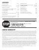
FOR MISSING PARTS OR ASSISTANCE, PLEASE CALL 1-800-864-6194 M-F 8am - 5pm CST.
Proof of purchase will be required.
TOOLS REQUIRED:
Adjustable Wrench
PARTS INCLUDED:
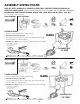
1. Remove components from the box and packing.
2. Attach Heat Shield to Suppor
t Bar
Line up heat shield over hole in support bar. Slide long bolt through
hole and attach nut. Wrench tighten.
3. Attach Hose to Burner - Refer to Connecting Regulator Hose Assembly
to Cooker on page 11.
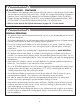
COOKER ASSEMBLY
1- Frame with
BG14 Bur
ner
KAB4
KAB6
TOOLS REQUIRED:
Adjustable Wrench
PARTS INCLUDED:
1 - Long Bolt
1 - Nut
1- Regulator
Hose Assembly
#M5HPR-30
1- Heat Sheild
1- Air Shutter
1- Spring
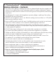
1- Frame with
BG14 Bur
ner
ASSEMBLED UNIT
ASSEMBLED UNIT
Turn Air Control Shutter to
adjust flame quality
Turn CLOCKWISE
W
rench Tighten
Place large end of spring
against Air Control Shutter
1. Remove components from the box and packing.
2. Attach Heat Shield to Suppor
t Bar
Line up heat shield over hole in support bar. Slide long bolt through
hole and attach nut. Wrench tighten.
3. Attach Hose to Burner - Refer to Connecting Regulator Hose Assembly
to Cooker on page 11.
COOKER ASSEMBLY
Turn Air Control Shutter to
adjust flame quality
Turn CLOCKWISE
W
rench Tighten
Place large end of spring
against Air Control Shutter
16" WIDE
22" WIDE
1- Brass Orifice
Connector
1 - Long Bolt
1 - Nut
1- Regulator
Hose Assembly
#M5HPR-30
1- Heat Sheild
1- Air Shutter
1- Spring1- Brass Orifice
Connector