
Owner's Manual


”
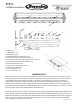
When using the t-slot mounting system. First determine your
mounting stud spacing. Adjust t-nuts (2) to desired length then
screw the 6mm X 40mm studs (10) into the t-nuts. Mark your
desired spacing onto the flat surface you are mounting to. Use a
1/4” or 7mm drill bit to drill mounting holes. Mount the BPB24 to
your mounting surface using the 6mm washers (8) and 6mm
nylon locking nuts (9) provided in hardware kit. You can also
use our optional PR-URM, PR-FRC175, and PR-FRC200 clamps
(sold separately) to mount to round tubbing. When mounting
the bottom half of the clamps to the BPB24. You will need to
use the 2 ea. 6mm X 12mm low profile socket head cap screws. (6)
PR-URM
2” to 1.5” PR-FRC200 2” clamps
PR-FRC175 1.75” clamps
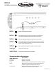
Use the 8mm X 12mm bolts (5) to attach
the mounting legs. Mounting legs (3) can
be installed in ether direction depending
on space constraints. When mounting with
opional clamps (PR-URM, PR-FRC200, and
PR-FRC175) use the hex bolts provided with
the clamps to mount the bottom half of the
clamps to the mounting legs.
PR-FRC200
2” clamps
PR-FRC175 1.75” clamps
PR-URM 2” to 1.5
”
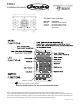
Warning:
If you are using the cast aluminum mounting legs to secure the Party Bar to your machine, the mounting legs must
FIRST be attached and tightened to the Party Bar before mounting it to your machine. Attaching the legs to the
machine first and then inserting the Party Bar between them can cause misalignment, spacing, and torque issues
that can cause damage to the mounting assembly resulting in a failure.
See Warning Below!
Adjustable T-Slot Mounting Options
End Mounting Options
with Cast Aluminum Legs
BPB24
Installation Instructions
Rev.9/24/2016 Pg. 4