
Specifications

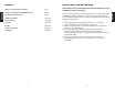

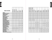

See
Model
Size
I
...
For
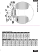
Length,. I
7.
Remove any slack
in
the
strap
by
feeding
it
out
of
the
mounting
base
on
the
loose
end
of
the
strap
opposite
the
buckle.
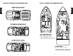
8.
Place
the
Bass
Tubes®
enclosure
on
the
mounting
bases
and
fasten
the
buckles
as
illustrated
in
figure
7.
The strap
should
loop
through
the
buckle and be
tightened
securely
by
holding
the
strap in place
with
one
hand and
pulling
the
loose
end
away
from
the
buckle,
but
against
the
cabinet.
Model
Length
6" 17"
8"
22"
10" 27"
12"
32"
Figure
7
Technical
Note:
Due
to
the
jarring
and
shifting
that
can occur
in
a vehicle,
the
mounting
straps may stretch
or
loosen. We recommend
that
you
check
the
straps
regularly
to
assure
that
your
Bass
Tubes®
enclosure
is
mounted
securely
in place.
9
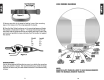
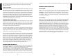
A100
WIRING
DIAGRAM
NOTE:
HI·LEY
Gil/TRACE
INPUT
(+)
HI·LEY
INPUT(-)
GUY/TRACE
HI·LEY
INPUT(-)
GREEN
HI·LEY
INPUT(+)
O"'OIW
REMOTE
LEVEL
CONTROL
-~
=--
-
16
GAU&E
BLACK
CHASSIS
GROUND
16
GAUGE
RED
BAmRY (12v+)
ORANGE
REMOTE
REMOVE
AUTO
TURN-ON
LOOP
TO
USE
ORANGE
REMOTE
WIRE
FOR
NORMAL
REMO"rE TURN-ON
10