Intel® Core 2 Duo/Pentium® Dual-Core/Celeron® 5XX series Mini ITX Motherboard MX965GME Version 1.02 User’s Manual http://www.bcmcom.
MX965GME FCC Statement THIS DEVICE COMPLIES WITH PART 15 FCC RULES. OPERATION IS SUBJECT TO THE FOLLOWING TWO CONDITIONS: (1) THIS DEVICE MAY NOT CAUSE HARMFUL INTERFERENCE. (2) THIS DEVICE MUST ACCEPT ANY INTERFERENCE RECEIVED INCLUDING INTERFERENCE THAT MAY CAUSE UNDESIRED OPERATION. THIS EQUIPMENT HAS BEEN TESTED AND FOUND TO COMPLY WITH THE LIMITS FOR A CLASS "A" DIGITAL DEVICE, PURSUANT TO PART 15 OF THE FCC RULES.
User’s Manual Disclaimer BCM Advanced Research reserves the right to make changes, without notice, to any product, including circuits and/or software described or contained in this manual in order to improve design and/or performance.
MX965GME Technical Support We want you to get the maximum performance from your products. So if you run into technical difficulties, we are here to help. For the most frequently asked questions, you can easily find answers in your product documentation. These answers are normally a lot more detailed than the ones we can give over the phone. So please consult the user’s manual first. To receive the latest version of the user’s manual; please visit our Web site at: http://www.bcmcom.
User’s Manual Product Warranty BCM warrants to you, the original purchaser, that each of its products will be free from defects in materials and workmanship for one year from the date of purchase. This warranty does not apply to any products which have been repaired or altered by persons other than repair personnel authorized by BCM, or which have been subject to misuse, abuse, accident or improper installation. BCM assumes no liability under the terms of this warranty as a consequence of such events.
CONTENTS FCC-B Radio Frequency Interference Statement .................................................................................. i Copyright Notice………... ....................................................................................................................... i Disclaimer……………………. ................................................................................................................ ii Life Support……... ……………………….................................................................
Chapter 1 Getting Started Thank you for choosing the MX965GME Mini ITX motherboard from BCM. Based on the innovative Intel® GME965 & ICH8M controllers for optimal system efficiency, the MX965GME accommodates the latest Intel® CoreTM 2 Duo / Pentium® Dual-Core / Celeron® 5XX series processors in Socket P and supports two 240-pin 533/667MHz DDRII DIMM to provide the maximum of 4GB memory capacity .
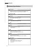
MX965GME Mainboard Specifications Processor - Intel Core 2 Duo/Pentium Dual-Core/Celeron 5 x x CPU in SocketP - Supports 3-pin CPU fan pin-header with Fan Speed Control - Supports Intel Dual Core Technology up to 800MHz Supported FSB - 533/667/800MHz Chipset - North Bridge: Intel GME965 chipset - South Bridge: Intel ICH8M chipset M e mo ry - DDR2 533/667 SDRAM (4GB Max) - 2 DDR2 DIMM slots (240pin / 1.8V) LAN - Supports 2 Gb Ethernet by Intel 82573L & 82566DC Audio - HDA Codec by Realtek ALC888 7.
Product Overview - 1 PS2 keyboard/mouse port - 3 audio jacks Onboard Connectors - 2 USB 2.0 connectors (4 ports) - 1 parallel port connector - 1 amplifer connector (4-pin) - 1 LVDS connector - 1 TV-out connector - 1 digital I/O connector (16GPIO) - 1 serial port connector - 1 front panel connector . 1 front lan led connector Slots - 1 PCI Express x4 slot (Must use a right angle PCI Express X4 riser card due to lack of clearance.
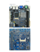
Product Overview Motherboard Layout MX965GME Mini ITX Motherboard
Hardware Setup Chapter 2 Hardware Setup This chapter provides you with the information about hardware setup procedures. While doing the installation, be careful in holding the components and follow the installation procedures. For some components, if you install in the wrong orientation, the components will not work properly. Use a grounded wrist strap before handling computer comp onen ts. Static el ectricity may damag e th e components.
MX965GME Quick Components Guide J5 JAUD2 JAMP1 DIMM1, 2 PCI 1 JLVDS1 PCIE4 JTV1 JSPI2 CPU FAN SYS FAN CON1 J4 JBAT1 J6 CPU SOCKET F_USB1, 2 ATX POWER JCF_SEL1 JLPT1 J7 J8 SATA1, 2 COM2 JCASE1 JFP1 IDE1 CF1 (BOTTOM SIDE) MX965GME Mini ITX Motherboard
Hardware Setup CPU (Central Processing Unit) The mainboard supports Intel ® Core 2 Duo/Pentium ® Dual-Core/Celeron ® 5xx processors in Socket P. When you are installing the CPU, make sure the CPU has a heat sink and a cooling fan attached on the top to prevent overheating. If you do not have the heat sink and cooling fan, contact your dealer to purchase and install them before turning on the computer. Important 1. Overheating will seriously damage the CPU and system.
MX965GME CPU & Cooler Installation for Socket P 1. Lo cate th e C PU s ock et on t h e mainboard. 2. Place the CPU on top of the socket. Make sure to align the gold arrow on the CPU with the arrow key on the socket. 3. Push the CPU down until its pins securely fit into the socket. 4. On the front end of the CPU socket is a locking mechanism designed into the form of a screw head. Make sure that you actuate or deactuate this mechanism with a screwdriver before and after installing the CPU.
Hardware Setup 5. Flip over the mainboard and locate the position of the CPU socket. 6. Install the backplate to the back of the CPU socket with holes aligned. CPU cooler backplate 7. The heatsink paste helps to enhance heat dissipation of the CPU. Before installing the cooler set (fan & heatsink bundled), make sure that you detach the shield of the heatsink paste under the cooler set. 8. Locate the four screw holes around the CPU socket where the CPU cooler backplate was installed.
MX965GME Memory The DIMM slots are intended for system memory modules. DDR2 240-pin, 1.8V 64x2=128 pin 56x2=112 pin Installing DDR2 Modules 1. The memory module has only one notch on the center and will only fit in the right orientation. 2. Insert the memory module vertically into the DIMM slot. Then push it in until the golden finger on the memory module is deeply inserted in the DIMM slot. Important You can barely see the golden finger if the memory module is properly inserted in the DIMM slot. 3.
Hardware Setup Power Supply ATX 20-Pin System Power Connector: ATX1 This connector allows you to connect to an ATX power supply. To connect to the ATX power supply, make sure the plug of the power supply is inserted in the proper orientation and the pins are aligned. Then push down the power supply firmly into the connector. ATX1 20 10 11 1 ATX1 Pin Definition PIN SIGNAL PIN SIGNAL 1 2 3 4 5 6 7 8 9 3.3V 3.3V GND 5V GND 5V GND PW_OK 5V_SB 11 12 13 14 15 3.
MX965GME Back Panel PS2 MS COM1 RGB VGA LAN2 LAN1 LINE-IN LINE-OUT PS2 KB HDMI DVI USB2 USB1 MIC Mouse/Keyboard The standard PS/2® mouse/keyboard DIN connector is for a PS/2® mouse/keyboard. Serial Port The serial port is a 16550A high speed communications port that sends/ receives 16 bytes FIFOs. You can attach a serial mouse or other serial devices directly to the connector. VGA Port The DB15-pin female connector is provided for monitor.
Hardware Setup Audio Ports These audio connectors are used for audio devices. You can differentiate the color of the audio jacks for different audio sound effects. Line-In (Blue) - Line In / Side-Surround Out in 7.1 channel mode, is used for extern al CD player, tap epl ayer or oth er aud io devices. Line-Out (Green) - Line Out, is a connector for speakers or headphones. Mic (Pink) - Mic, is a connector for microphones. HDMI and DVI Ports This The HDMI and DVI ports are for digital video output.
MX965GME Connector Chassis Intrusion Connector: JCASE1 This connector connects to the chassis intrusion switch cable. If the chassis is opened, the chassis intrusion mechanism will be activated. The system will record this status and show a warning message on the screen. To clear the warning, you must enter the BIOS utility and clear the record. GND CINTRU 1 2 JCASE1 IDE Connector: IDE1 This connector supports IDE hard disk drives, optical disk drives and other IDE devices.
Hardware Setup Digital IO Connector: J4 The J4 is designed to connect the General-Purpose Input/Output (GPIO) peripheral module. Pin Definition J4 19 20 1 2 PIN SIGNAL PIN SIGNAL 1 3 5 VCC3 N_GPIO10 N_GPIO11 2 4 6 VCC5 N_GPIO20 N_GPIO21 7 9 11 13 15 17 19 N_GPIO12 N_GPIO13 N_GPIO14 N_GPIO15 N_GPIO16 N_GPIO17 GND 8 10 12 14 16 18 20 N_GPIO22 N_GPIO23 N_GPIO24 N_GPIO25 N_GPIO26 N_GPIO27 NC Serial ATA II Connector: SATA1, SATA2 This connector is a high-speed Serial ATA II interface port.
MX965GME Audio Amplifier Connector: JAMP1 The JAMP1 is used to connect audio amplifiers to enhance audio performance. JAMP1 1 PIN SIGNAL 1 AMP_L- 2 3 4 AMP_L+ AMP_RAMP_R+ Front Audio Connector: JAUD2 The JAUD2 is used to connect audio to front panel.
Hardware Setup Fan Power Connectors: CPUFAN1, SYSFAN1 The fan power connectors support system cooling fan with +12V. When connecting the wire to the connectors, always note that the red wire is the positive and should be connected to the +12V; the black wire is Ground and should be connected to GND. If the mainboard has a System Hardware Monitor chipset on-board, you must use a specially designed fan with speed sensor to take advantage of the CPU fan control.
MX965GME TV-Out Connector: JTV1 This connector is for you to attach an optional TV-Out bracket that offers two types of TV-Out connectors: S-Video and RCA Composite connectors. Select the appropriate one to connect the standard television or the HDTV (High-Definition TeleVision).
Hardware Setup LVDS Flat Panel Connector: JLVDS1 The LVDS (Low Voltage Differential Signal) connector provides a digital interface typically used with flat panels.
MX965GME Front USB Connector: F_USB1, F_USB2 This connector, compliant with Intel ® I/O Connectivity Design Guide, is ideal for connecting high-speed USB interface peripherals such as USB HDD, digital cameras, MP3 players, printers, modems and the like. Pin Definition 1 2 9 10 F_USB1/2 PIN SIGNAL PIN SIGNAL 1 VCC 2 VCC 3 USB0- 4 USB1- 5 USB0+ 6 USB1+ 7 GND 8 GND 9 Key (no pin) 10 NC USB 2.
Hardware Setup Serial Port Connector: COM 2 This connector is a 16550A high speed communications port that sends/receives 16 bytes FIFOs. You can attach a serial device to it through the optional serial port bracket.
MX965GME Jumper 9 10 Front Panel LAN LED: J8 Provide LAN Status to the front panel. 1 2 Pin Definition Pin Description Pin Description 1 LAN1_LED 2 LAN2_LED 3 LAN1_LED_1 4 LAN2_LED_1 5 LAN1_LED 6 LAN2_LED 7 LAN1_LED_11 8 LAN2_LED_11 9 NC 10 NC COM Port Power Jumpers: J5, J6 These jumpers specify the operation voltage of the onboard serial ports.
Hardware Setup Slot PCI (Peripheral Component Interconnect) Express Slot The PCI Express x 4 slot supports PCI Express interface expansion card up to 2.0 GB/s transfer rate. (Note: Must use a right angle PCIE x4 riser card when using this slot.) The CON1 is Mini PCI-E connector for wireless LAN, TV tuner, and Robson NAND Flash.
MX965GME CompactFlash Card Slot: CF1 This CompactFlash slot shares one channel of the IDE controller. You can install one CompactFlash typeI / type II device. CF1 CF Mode Selecting Jumper: JCF_SEL1 This jumper is used to select Master/ Slave mode of the CF device. JCF_SEL1 1 1 1 Master Slave Important * The CF1 slot and the IDE1 connector shares and uses the same channel. CF1 and IDE1 can support up to 2 IDE devices without CF device or 1 IDE device with 1 CF device.
BIOS Setup Chapter 3 BIOS Setup This chapter provides information on the BIOS Setup program and allows you to configure the system for optimum use. You may need to run the Setup program when: An error message appears on the screen during the system booting up, and requests you to run SETUP. You want to change the default settings for customized features.
MX965GME Entering Setup Power on the computer and the system will start POST (Power On Self Test) process. When the message below appears on the screen, press key to enter Setup. Press Del to enter SETUP If the message disappears before you respond and you still wish to enter Setup, restart the system by turning it OFF and On or pressing the RESET button. You may also restart the system by simultaneously pressing , , and keys. Important 1.
BIOS Setup Control Keys <↑> <↓> <←> <→> <+/PU> <-/PD> Move to the previous item Move to the next item Move to the item in the left hand Move to the item in the right hand Select the item Jumps to the Exit menu or returns to the main menu from a submenu Increase the numeric value or make changes Decrease the numeric value or make changes Load Optimized Defaults Load Fail-Safe Defaults Save all the CMOS changes and exit Getting Help After entering the Setup menu, the first men
MX965GME The Menu Bar Main Use this menu for basic system configurations, such as time, date etc. Advanced Use this menu to set up the items of special enhanced features. Boot Use this menu to specify the priority of boot devices. Security Use this menu to set supervisor and user passwords. Chipset This menu controls the advanced features of the onboard Northbridge and Southbridge.
BIOS Setup Main AMI BIOS, Processor, System Memory These items show the firmware and hardware specifications of your system. Read only. System Time The time format is . System Date The date format is , .
MX965GME Advanced CPU Configuration These items show the advanced specifications of your CPU. Read only.
BIOS Setup IDE Configuration ATA/IDE Configuration This setting specifies the modes of the PATA & SATA ports. Configure SATA as s This setting specifies the function of the on-chip SATA controller.
MX965GME Primary/Secondary/Third/Fourth IDE Master/Slave [Type] Press PgUp/<+> or PgDn/<-> to select [Manual], [None] or [Auto] type. Note that the specifications of your drive must match with the drive table. The hard disk will not work properly if you enter improper information for this category. If your hard disk drive type is not matched or listed, you can use [Manual] to define your own drive type manually.
BIOS Setup Super IO Configuration Serial Port 1 / 2 Address Select an address and a corresponding interrupt for the serial port 1/2. Parallel Port Address This setting specifies the I/O port address and IRQ of the onboard parallel port. Chassis Intrusion The field enables or disables the feature of recording the chassis intrusion status and issuing a warning message if the chassis is once opened. To clear the warning message, set the field to [Reset].
MX965GME Hardware Health Configuration System 1 / 2 Temperature, CPU Temperature, CPUFAN Speed, Vcore, AVCC, 3VCC, +12V, 5V, VSB, VBAT These items display the current status of all of the monitored hardware devices/components such as CPU voltage, temperatures and all fans’ speeds. CPUFAN0 / CPUFAN1 Mode Setting These settings specify the operation mode of the CPU fans. CPUFAN0 / CPUFAN1 PWM Control These settings control the PWM duty cycle of the CPU fans.
BIOS Setup ACPI Configuration Suspend Mode This item specifies the power saving modes for ACPI function. If your operating system supports ACPI, you can choose to enter the Standby mode in S1 (POS) or S3 (STR) fashion through the setting of this field. Options are: [S1 (POS)] The S1 sleep mode is a low power state. In this state, no system context is lost (CPU or chipset) and hardware maintains all system context.
MX965GME APM Configuration Power M anagement/APM Setting to [Enabled] will activate an Advanced Power Management (APM) device to enhance Max Saving mode and stop CPU internal clock. Power Button Mode This setting controls the operation of the power button. Resume On LAN This field specifies whether the system will be awakened from power saving modes when activity or input signal of onboard LAN is detected.
BIOS Setup Intel Robson Configuration Intel Robson Robson is the code name for a new Intel platform technology that uses nonvolatile memory (Flash memory) to increase system responsiveness, make multi-tasking faster, and extend battery life. Intel Robson technology is poised to eliminate many of the bottlenecks associated with HDD latency.
MX965GME Remote Access Configuration Remote Access This field allows you to Enabled or Disabled Remote Access for console redirection via serial ports. Set the desired port and setting in each field.
BIOS Setup Trusted Computing TCG/TPM Support This setting controls the Trusted Platform Module (TPM) designed by the Trusted Computing Group (TCG). TPMs are special-purpose integrated circuits (ICs) built into a variety of platforms to enable strong user authentication and machine attestation—essential to prevent inappropriate access to confidential and sensitive information and to protect against compromised networks.
MX965GME USB Configuration Legacy USB Support Set to [Enabled] if you need to use any USB 1.1/2.0 device in the operating system that does not support or have any USB 1.1/2.0 driver installed, such as DOS and SCO Unix. USB 2.0 Controller Mode This setting specifies the operation mode of the onboard USB 2.0 controller.
BIOS Setup Boot Boot Settings Configuration 3-17
MX965GME Quick Boot Enabling this setting will cause the BIOS power-on self test routine to skip some of its tests during bootup for faster system boot. Quiet Boot This BIOS feature determines if the BIOS should hide the normal POST messages with the motherboard or system manufacturer's full-screen logo. When it is enabled, the BIOS will display the full-screen logo during the boot-up sequence, hiding normal POST messages.
BIOS Setup ture" Interrupt 19. Therefore, you will not be able to boot operating systems from any bootable disks attached to these host adaptors. Nor will you be able to gain access to their ROM setup utilities. Flash Write Protection Select [Enabled] if you need to program data into the flash chip. Select [Disabled] if you need to protect the data from being overwritten. Chassis Instruction Select [Enabled] to enable the chassis instruction function.
MX965GME Removable Drives 1st Drive This setting allows users to set the priority of the removable devices. First press to enter the sub-menu. Then you may use the arrow keys ( ↑↓ ) to select the desired device, then press <+>, <-> or , key to move it up/down in the priority list.
BIOS Setup Security Supervisor Password / Change Supervisor Password Supervisor Password controls access to the BIOS Setup utility. These settings allow you to set or change the supervisor password. User Password / Change User Password User Password controls access to the system at boot. These settings allow you to set or change the user password.
MX965GME Chipset 3-22
BIOS Setup North Bridge Configuration Boot Graphics Adapter Priority This item specifies which VGA card is your primary graphics adapter. Internal Graphics Mode Select The field specifies the size of system memory allocated for video memory. PEG Port This setting allows you to select whether to use the onchip graphics processor or the PCI Express card. When set to [Auto], the BIOS checks to see if a PCI Express graphics card is installed.
MX965GME Video Function Configuration DVMT Mode Select Intel's Dynamic Video Memory Technology (DVMT) allows the system to dynamically allocate memory resources according to the demands of the system at any point in time. The key idea in DVMT is to improve the efficiency of the memory allocated to either system or graphics processor. It is recommended that you set this BIOS feature to DVMT Mode for maximum performance.
BIOS Setup South Bridge Configuration USB Functions This setting specifies the function of the onboard USB controller. USB 2.0 Controller Set to [Enabled] if you need to use any USB 2.0 device in the operating system that does not support or have any USB 2.0 driver installed, such as DOS and SCO Unix. GbE Controller This setting disables/enables the onboard Gigabit Ethernet controller.
MX965GME Exit Save Changes and Exit Save changes to CMOS and exit the Setup Utility. Discard Changes and Exit Abandon all changes and exit the Setup Utility. Discard Changes Abandon all changes and continue with the Setup Utility. Load Optimal Defaults Use this menu to load the default values set by the mainboard manufacturer specifically for optimal performance of the mainboard. Load Failsafe Defaults Use this menu to load the default values set by the BIOS vendor for stable system performance.