P4 Socket 478 Motherboard IN845GVD User’s Manual http://www.bcmcom.
Declaration Rights: No part of this manual, including but not limited to the products and software described in it, may be reproduced, transmitted, transcribes, stored in a retrieval system, or translated in any form or by any means without the expressed written permission from the manufacturer.
Compliance & Certificate Compliance & Certificate ISO 9001 Certificate: This device was produced in our plant with advanced quality system certified by DNV QA Ltd. in according to ISO 9001. This Certificate is valid for: DESIGN & MANUFACTURE OF MOTHERBOARD AND PERSONAL COMPUTERS. CE Declaration: CE marking is a visible declaration by the manufacturer or his authorized representatives that the electrical equipment to which it relates satisfies all the provisions of the 1994 Regulations.
Easy Installation Ea s y Ins ta lla tio n Easy Installation Steps The following “Easy Installation” steps are for users accustomed to the assembly of a computer system. For those individuals requiring more specific information, please refer to the more detailed descriptions located within the latter chapters of this manual. Note: You must keep your power cable unplugged until the following installation steps are completed.
TABLE OF CONTENT USER’S NOTICE MANUAL REVISION INFORMATION COOLING SOLUTIONS CHAPTER 1 INTRODUCTION OF IN845GVD MOTHERBOARD 1-1 FEATURE OF MOTHERBOARD 1-2 SPECIFICATION 1-3 LAYOUT DIAGRAM & JUMPER SETTING CHAPTER 2 HARDWARE INSTALLATION 2-1 HARDWARE INSTALLATION STEPS 2-2 CHECKING MOTHERBOARD'S JUMPER SETTING 2-3 INSTALL CPU 2-3-1 GLOSSARY 2-3-2 ABOUT INTEL PENTIUM 4 478-PIN CPU 2-4 INSTALL MEMORY 2-5 EXPANSION CARD 2-5-1 PROCEDURE FOR EXPANSION CARD INSTALLATION 2-5-2 ASSIGNING IRQ FOR EXPANSION CARD 2-5-3
USER’S NOTICE COPYRIGHT OF THIS MANUAL BELONGS TO THE MANUFACTURER. NO PART OF THIS MANUAL, INCLUDING THE PRODUCTS AND SOFTWARE DESCRIBED IN IT MAY BE REPRODUCED, TRANSMITTED OR TRANSLATED INTO ANY LANGUAGE IN ANY FORM OR BY ANY MEANS WITHOUT WRITTEN PERMISSION OF THE MANUFACTURER. THIS MANUAL CONTAINS ALL INFORMATION NECESSARY TO USE OF RX845GL/IN845GL MOTHER-BOARD AND WE DO ASSURE THIS MANUAL CONTENT AS MANY INFORMATION AS POSSIBLE, BUT WE RESERVE RIGHT TO CHANGE, UPDATE ANYTIME WITHOUT PRIOR NOTICE.
Intel Pentium 4 Processor Family Cooling Solutions As processor technology pushes to faster speeds and higher performance, thermal management becomes increasingly crucial when building computer systems. Maintaining the proper thermal environment is key to reliable, long-term system operation. The overall goal in providing the proper thermal environment is keeping the processor below its specified maximum case temperature.
Chapter 1 Introduction of IN845GVD Motherboard 1-1 Feature of motherboard The IN845GVD motherboard has been updated to support Intel latest Celeron D and Intel Pentium 4 Processor in 478 Pin Package up to 533Mhz FSB Processor with Hyper-Threading Technology support, the Intel 845GV Chipset delivers a high performance and professional platform solution. Which utilize the P4 Socket 478 design and the memory size expandable to 2.0GB.
1-2 Specification Spec Description Design ∗ Chipset ∗ CPU Socket (mPGA478B Socket) Graphics Memory Socket Expansion Slot & Headers Integrate IDE LAN On Board Audio BIOS Multi I/O ∗ ∗ ∗ ∗ ∗ ∗ ∗ ∗ ∗ ∗ ∗ ∗ ∗ ∗ ∗ ∗ ∗ ∗ ∗ ∗ ∗ ∗ ∗ ∗ ∗ ∗ ∗ ∗ Micro ATX form factor 4 layers PCB size: 9.5”(W) x 9(D) (24.4x23.
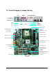
1-3 Layout Diagram & Jumper Setting LAN GAME/MIDI PORT PRINT PS/2 MOUSE PS/2 Keyboard USB COM1 VGA ATX 12V Power Conn. MIC LINE-IN LINE-OUT CPU 478 Socket PS2 KB/Mouse Port CPU FAN USB Port /LAN Connector ATX P9 Power Conn. DDR DIMM X2 ATX Power Conn. COM2 Connector Floppy Connector PC99 Back Panel ATA 100 IDE Conn.
Jumpers Jumper JP4 JP5 JP7 JP8 Name CMOS RAM Clear BIOS Protect LCD P4 Power Select LCD P2 Power Select Description 3-pin Block 4-pin Block 6-pin Block 3-pin Block Page P.7 P.8 P.21 P.21 Connectors Connector ATXPWR ATX12V ATXP9 PS2 KB/MOUSE Name ATX Power Connector ATX 12V Power Connector ATX P9 Power Connector PS/2 Mouse & PS/2 Keyboard Connector Description 20-pin Block 4-pin Block 6-pin Block 6-pin Female Page P.13 P.14 P.14 P.
Chapter 2 Hardware installation 2-1 Hardware installation Steps Before using your computer, you had better complete the following steps: 1. Check motherboard jumper setting 2. Install CPU and Fan 3. Install System Memory (DIMM) 4. Install Expansion cards 5. Connect IDE and Floppy cables, Front Panel /Back Panel cable 6. Connect ATX Power cable 7. Power-On and Load Standard Default 8. Reboot 9. Install Operating System 10.
(2) BIOS Protect (4-pin) : JP5 1 4 JP5 1 4 JP5 1-2 boot block protect 2-3 Un-protect (Default) 1 3-4 all write protect FWH Write Protect Setting 8 4 JP5
2-3 Install CPU 2-3-1 Glossary Chipset (or core logic) - two or more integrated circuits which control the interfaces between the system processor, RAM, I/O devises, and adapter cards. Processor slot/socket - the slot or socket used to mount the system processor on the motherboard. Slot (AGP, PCI, ISA, RAM) - the slots used to mount adapter cards and system RAM. PCI - Peripheral Component Interconnect - a high speed interface for video cards, sound cards, network interface cards, and modems; runs at 33MHz.
2-3-2 About Intel Pentium 4 478-pin CPU This motherboard provides a 478-pin surface mount, Zero Insertion Force (ZIF) socket, referred to as the mPGA478B socket supports Intel Pentium 4 processor in the 478 Pin package utilizes Flip-Chip Pin Grid Array (FC-PGA2) package technology. The CPU should have a cooling FAN attached to prevent overheating. If this is not the case, then purchase a correct cooling FAN before you turn on your system.
2-4 Install Memory This motherboard provides two 184-pin DUAL INLINE MEMORY MODULES (DIMM) sites for memory expansion available from minimum memory size of 64MB to maximum memory size of 2.0GB DDR SDRAM. Valid Memory Configurations Bank 184-Pin DIMM Bank 0, 1 (DDR1) Bank 2, 3 (DDR2) Total NOTE! DDR333/DDR266 DDR SDRAM Module DDR333/DDR266 DDR SDRAM Module System Memory (Max. 2.0GB) Total Memory X1 64MB∼1.0GB X1 64MB∼1.0GB 2 64MB∼2.
2-5 Expansion Cards WARNING! Turn off your power when adding or removing expansion cards or other system components. Failure to do so may cause severe damage to both your motherboard and expansion cards. 2-5-1 Procedure For Expansion Card Installation 1. Read the documentation for your expansion card and make any necessary hardware or software setting for your expansion card such as jumpers. 2. Remove your computer’s cover and the bracket plate on the slot you intend to use. 3.
2-5-3 Interrupt Request Table For This Motherboard Interrupt request are shared as shown the table below: INT A INT B INT C INT D INT E √ Slot 1 Slot 2 Slot 3 Onboard VGA Onboard LAN Onboard USB 1 Onboard USB 2 Onboard USB 3 AC97/MC97 IMPORTANT! INT F INT G INT H √ √ √ √ √ √ √ √ If using PCI cards on shared slots, make sure that the drivers support “Shared IRQ” or that the cards don’t need IRQ assignments.
(2) ATX 12V Power Connector (4-pin block) : ATX12V This is a new defined 4-pins connector that usually comes with ATX Power Supply. The ATX Power Supply which fully support Pentium 4 processor must including this connector for support extra 12V voltage to maintain system power consumption. Without this connector might cause system unstable because the power supply can not provide sufficient current for system.
(8) (9) Audio and Game Connector : GAME This Connector are 3 phone Jack for LINE-OUT, LINE-IN, MIC and a 15-pin D-Subminiature Receptacle Connector for joystick/MIDI Device. Audio output to speaker Line-out : Audio input to sound chip Line-in : Microphone Connector MIC : Game/MIDI : For joystick or MIDI Device VGA Connector (15-pin D-Sub) Connector: VGA VGA is the 15-pin D-Subminiature female connector for display monitor. (10) Serial Port COM1: COM1 COM1 is the 9-pin D-Subminiature mail connector.
(12) Primary IDE Connector (40-pin block): IDE1 This connector supports the provided IDE hard disk ribbon cable. After connecting the single plug end to motherboard, connect the two plugs at other end to your hard disk(s). If you install two hard disks, you must configure the second drive to Slave mode by setting its jumpers accordingly. Please refer to the documentation of your hard disk for the jumper settings.
2-6-2 Headers (1) Serial Port2 COM2 Header (9-pin) : COM2 COM2 SIGNAL DCD#1 C RXD#1 C TXD1 C DTR#1 C GND Pin 1 Serial Port2 COM2 Header (2) PIN 1 2 3 4 5 6 7 8 9 SIGNAL DSR#1 C RTS#1 C CTS#1 C RI#1 C Note: Orient the read marking on the COM2 ribbon cable to pin 1 Line-Out, MIC Header (9-pin): AUDIO This header connect to Front Panel Line-out, MIC connector with cable.
(5) Reset switch lead: RESET This 2-pin connector connects to the case-mounted reset switch for rebooting your computer without having to turn off your power switch. This is a preferred method of rebooting in order to prolong the lift of the system’s power supply. See the figure below. (6) Speaker connector: SPEAKER This 4-pin connector connects to the case-mounted speaker. See the figure below. (7) Power LED: PWR LED The Power LED is light on while the system power is on.
(10) Chassis Intrusion SIGNAL GND CHASSIS# 11) PIN 1 2 FAN Speed Headers (3-pin) : SYSFAN, SYSFAN2, CPUFAN These connectors support cooling fans of 350mA (4.2 Watts) or less, depending on the fan manufacturer, the wire and plug may be different. The red wire should be positive, while the black should be ground. Connect the fan’s plug to the board taking into consideration the polarity of connector.
(13) CD Audio-In Headers (4-pin) : CDIN CDIN are the connectors for CD-Audio Input signal. Please connect it to CD-ROM CDAudio output connector.
(15) LCD P2 Voltage Select 3 pin : JP8 JP8 1 1-2 LCD P2 +5V 2-3 LCD P2 +12V Default=1-2 3 LCD P2 Voltage Select (16) LCD P4 Pin Voltage Select 6 pin : JP7 JP7 1 1-2 LCD-P4=+3.
2-7 Starting Up Your Computer 1. After all connection are made, close your computer case cover. 2. Be sure all the switch are off, and check that the power supply input voltage is set to the local voltage, usually in-put voltage is 220V∼240V or 110V∼120V depending on your country’s voltage used. 3. Connect the power supply cord into the power supply located on the back of your system case according to your system user’s manual. 4. Turn on your peripheral as following order: a. Your monitor. b.
Chapter 3 Introducing BIOS The BIOS is a program located on a Flash Memory on the motherboard. This program is a bridge between motherboard and operating system. When starting the computer, the BIOS program gain control. The BIOS first operates an auto-diagnostic test called POST (power on self test) for all the necessary hardware, it detects the entire hardware device and configures the parameters of the hardware synchronization.
3-3 The Main Menu Once you enter Whizpro® BIOS CMOS Setup Utility, the Main Menu (Figure 3-1) will appear on the screen. The Main Menu allows you to select from fourteen setup functions and two exit choices. Use arrow keys to select among the items and press to accept or enter the sub-menu. Whizpro BIOS from Whizpro Technology Co., Ltd.
Enable/Disable peripheral controller, configure serial and parallel ports. Power Management Configure Power Management modes, timers, events, device control… PCI & PnP PnP OS flag, PnP configuration data, ISA memory & IRQ reservation. Hardware Monitor This entry shows your current system health status. Restore Default Settings Load factory default or fail-safe settings. Exit Leave SETUP program, system will restart after saving setting to CMOS.
3-4 General Configuration The items in General Configuration Menu are divided into several categories. Each category includes no, one or more than one setup items. Use the arrow keys to highlight the item and then use the or keys to select the value you want in each item. Whizpro BIOS SETUP Utility General Configuration Date Time : 03/04/02005 : 18:20:00 Floppy A : 1.
First/Second/Third/Fourth Boot Device The BIOS attempts to load the operating system from the devices in the sequence selected in these items. The settings are Floppy, LS/ZIP, HDD-0/HDD-1/HDD-3, SCSI, CDROM, LAD and Disabled. Power Up NumLock Status The default value is On. On (default) Keypad is numeric keys. Off Keypad is arrow keys. Power Up Floppy Seek During POST, BIOS will determine if the floppy disk drive installed is 40 or 80 tracks. 360K type is 40 tracks while 760K, 1.2M and 1.
3-5 Advanced Configuration Whizpro BIOS SETUP Utility Advanced Configuration IDE Drive Delay : Disabled Multi Sector Transfer : Auto Hyper-Threading Technology : Disabled Memory Test : Quick Halt on POST Error : Any error Video BIOS Cacheable : Disabled Typematic Rate Setting : Disabled Typematic Rate : -Typematic Delay : -- Quiet Boot : Disabled Frame Buffer for IGD : 32MB Internal Display Output: VBIOS Default LCD Panel Resolution : 01 TV Format : Auto ↑↓ ENTER ESC F9 F10 : : : : : Select a menu e
Video BIOS Cacheable Allow to select video BIOS cache enable or disable. Typematic Rate Settings Allow to enable or disable typematic rate. Quiet Boot Enable to display only error messages during boot. Frame Buffer for IGD Allocate a frame buffer for on chip integrate graphics. Internal Display Output Select boot display device. LCD Panel Resolution Select the panel type correspond to the panel native display resolution. TV Format Select TV Format Spread Spectrum Enable/ Disable spread spectum.
3-6 Primary IDE Drives/ Secondary IDE Drives Whizpro BIOS SETUP Utility Primary IDE Drives Primary Master Drive Type : None Drive Mode : -UDMA Mode : -Cylindre : -Head : -Sector : -Size : -Primary Slave Drive Type : None Drive Mode : -UDMA Mode : -Cylindre : -Head : -- ↑↓ ENTER ESC F9 F10 Sector : -Size : -- Drive Type Select from None, Auto or Manual. Drive Mode Selecting Drive Mode . UDMA Mode Select Enabled or Disabled UDMA mode. Cylinder Enter drive cylinder.
Whizpro BIOS SETUP Utility Secondary IDE Drives Secondary Master Drive Type : None Drive Mode : -UDMA Mode : -Cylindre : -Head : -Sector : -Size : -Secondary Slave Drive Type : None Drive Mode : -UDMA Mode : -Cylindre : -Head : -- ↑↓ ENTER ESC F9 F10 Sector : -Size : -- Drive Type Select from None, Auto or Manual. Drive Mode Selecting Drive Mode . UDMA Mode Select Enabled or Disabled UDMA mode. Cylinder Enter drive cylinder. Head Enter drive number of head. Sector Enter drive sector number.
3-7 Peripherals Whizpro BIOS SETUP Utility Peripherals Floppy Controller : Enabled Primary IDE : Enabled Secondary IDE : Enabled Serial Port 1 : Enabled Serial Port 2 : Enabled Mode : -Parallèle Port : Enabled Mode : ECP DMA : Onboard USB Controller : Enabled USB Legacy Support : -USB Disk Emulation : -- AC97 Audio : Disabled Onboard LAN Controller : Enabled LAN Boot Rom: -- Game Port and Midi Port : Enabled ↑↓ ENTER ESC F9 F10 Game Port IO : 200-207h MIDI Port IO : 330-331h MIDI Port IRQ : IRQ3 Flo
Select an address and corresponding interrupt for the first and the second serial ports. The settings are: 3F8/IRQ4, 2E8/IRQ3, 3E8/IRQ4, 2F8/IRQ3, Disabled, Auto. UART2 Mode This item allows you to determine which InfraRed(IR) function of the onboard I/O chip, this functions uses. Parallel Port There is a built-in parallel port on the on-board Super I/O chipset that Provides Standard, ECP, and EPP features.
3-8 Power Management Setup The Power Management Setup allows you to configure your system to most effectively save energy saving while operating in a manner consistent with your own style of computer use. Whizpro BIOS SETUP Utility Power Management Power Management : Enabled Stand-by Timer : Off Suspend Timer : Off Hard Disk Power Down : Disable Video Off : Disabled Power Button : Delay 4 Sec.
Pressing the power button for more than 4 seconds forces the system to enter the Soft-Off state. The settings are: Delay 4 Sec, Instant-Off. Modem Use IRQ This determines the IRQ in which the MODEM can use. The settings are: 3, 4, 5, 7, 9, 10, 11, NA. Wake On PME When enabled, BIOS will enable PCI devices to drive PME signal to wake up the system. Wake On RI When enabled, an input signal from the ring indicator line will awaken the system from soft-off state.
3-9 PCI PnP Configuration Whizpro BIOS SETUP Utility PCI & PnP PnP OS Installed : Yes Reset Configure Data : No PCI VGA Palette Snoop : Disabled Reserved ISA Memory Space C800-CC00: No CC00-D000: No D000-D400: No D400-D800: No D800-DC00: No DC00-E000: No IRQ Reserved to ISA Device IRQ: None IRQ: None IRQ: None ↑↓ ENTER ESC F9 F10 IRQ: None : : : : : Select a menu enter a menu quit & exit load default CMOS settings save settings and exit Reset Configuration Data Normally, you leave this field Disable
3-10 Hardware Monitor This section shows the Status of you CPU, Fan, Warning for overall system status. This is only available if there is Hardware Monitor onboard. Whizpro BIOS SETUP Utility Hardware Monitor Chassis Intrusion Detect: Disabled CPU Voltage : FSB Voltage : 3.3 Volt : 5.0 Volt : 12.0 Volt : -12.0 Volt : -5.
3-11 Restore Manufacture Settings When you press on this item, you get confirmation dialog box with a message similar to: Restore Manufacture Settings (Y/N)? N Pressing loads the BIOS default values for the most stable, minimal-performance system operations.
Mechanical Draw 39