
Specifications


Page 2 of 10
75.0082.05 20080125
MECHANICAL
INSTALLATION
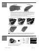
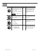
1. Remove the left endcap by removing the two Phillips head screws. Use the Allen key provided in the
screw kit to loosen the setscrew. Finally, slide the sensor from the mounting bracket.
REMOVE ENDCAP LOOSEN SETSCREW REMOVE SENSOR FROM BRACKET
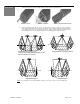
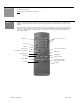
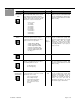
2. Select a mounting position for the sensor. For single door or a pair of doors, the sensor should be
centered with relation to the door opening. If the DK-12 is used on any door with an opening greater than
6’, it is highly recommended to use more than one DK-12. Pattern selections will depend on the door and
the mounting position. See the chart and diagram on the following pages for pattern selection.
NOTE
: Be sure that there are no objects within the view of the sensor lenses, such as a door-operating arm.
Left Hand Swin
g
Door
Double Swing Door (opening less than 6’)
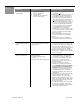
Ri
g
ht Hand Swin
g
Door
Double Swing Door (opening over 6’)
See page 7 for selecting the pulsing frequency of two
DK-12’s located next to each other