
Specifications


Page 3 of 10
75.0082.05 20080125
ELECTRICAL
INSTALLATION
MECHANICAL
INSTALLATION
(CON’T)
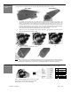
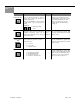
The mounting bracket may be to a header or to the ceiling. Select the location for mounting, and secure solidly with
screws provided. To mount the unit to the ceiling, the two plastic plugs will need to be removed.
WALL MOUNT CEILING MOUNT
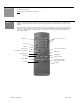
3. The installer must provide means for routing wires from the sensor to the inside of the header. The
terminal block is located at the left end of the sensor. At the back edge of the left and right end covers,
there is a small punch out slot to allow the concealed passage of wire into the sensor. A slot is also
provided at the top of the sensor, should wires need to be routed from the opposite end of the sensor.
Locate the wire passage hole on the header to keep it concealed. Once the hole is located and drilled,
pull the 6-conductor wire from the header to the sensor, and leave a few inches hanging out.
Do not drill holes in the aluminum-mounting bracket. (This voids warranty)
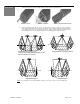
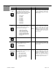
4. Slide the sensor into the mounting bracket at the desired angle. The greater the mounting angle, the
further the pattern will be from the threshold.
20° (standard position) 26° 32°
5. Tighten the setscrew and replace the endcap.
NOTE
: BEA recommends the use of the WHU (weather protection hood) for any DK-12 that is installed outside and
is exposed to direct weather. The circuit board of the DK-12 is not waterproof; therefore, it is susceptible to
water damage. Any DK-12 that is returned due to water damage will be considered out of warranty.
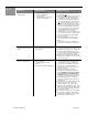
At the left side of the sensor, remove the 7 pin terminal connector by pulling it straight out. Connect as shown:
PIN WIRE COLOR
1 RED
2 BLACK
3 WHITE
4 GREEN
5
6 BROWN
7 BLUE
Refer to the wiring diagram in the respective User’s Guide
for the type of Lockout Module being used (i.e. LO-21,
LO-21U, MC-15, etc.) for all necessary wiring.