
User`s guide


75.5134.10 EN 20110519 Page 11 of 13
TROUBLE-
SHOOTING
BODYGUARD
DEPTH
PATTERNS -
Cont.
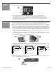
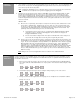
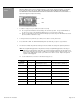
Row 1 (spots 1 through 6), are on during open door position and off during closed door position.
1
2
3
4
5
6
7
8
9
10
11
12
13
14
15
16
17
18
19
20
21
22
23
24
1
2
3
4
5
6
7
8
9
10
11
12
13
14
15
16
17
18
19
20
21
22
23
24
1
2
3
4
5
6
7
8
9
10
11
12
13
14
15
16
17
18
19
20
21
22
23
24
Bodyguard will not set-up
upon initial powering
PROBLEM PROBABLE CAUSE CORRECTIVE ACTION
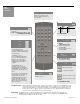
1. Check terminals 1 & 2 for proper voltage
12 to 24 V AC/DC +
10%.
2. Make certain that the field of detection is all
clear during the set-up and that all lenses
are installed on the Bodyguard. If detection
is encountered upon initial set-up, the
Bodyguard will continuously flash Green at
+
2 Hz. The Bodyguard will also not set-up
if permanent stationary objects are
extremely close to the sensor. Ensure that,
not only is the detection field all clear, but
that the sensor is mounted properly (using
the Bodyguard mounting block if
NECESSARY).
3. Ensure that no high intensity lighting is in
the immediate area of the sensor.
1. Improper input voltage
2. Bodyguard is in detection
3. Potential interferences from high
intensity lighting
Door will not open once set-
up has been completed.
1. Bodyguard is in detection.
2. Improper wiring
3. Lockout safety beams are in
detection
4. Improper relay output configuration
1. Ensure that there is no detection occurring
at the Bodyguard. If the Red LED is on
steady, there is detection. Make sure there
have been no changes in the field of
detection since set-up. If permanent
changes have occurred, launch a new set-
up and re-test door.
CAUTION
: THERE POSSIBLY MAY BE NO
SAFETY ON THE DOOR WHEN
THIS TEST IS PERFORMED.
2. Remove the output wires (common,
normally open, normally closed) from the
Bodyguard. Activate the door control, if the
door opens, the fault exists with Bodyguard
or related wiring. If door does not open, the
faults may exist with the door control or it’s
related wiring.
3. Disconnect the green & blue wires from the
LO-21 to the door control safety and
common terminals. If door opens when
triggered, fault lies within the lockout safety
beam set, or possibly with the LO-21. Refer
to the LO-21 troubleshooting procedures in
the respective manual.
4. Ensure proper relay output setting. Refer to
page 6. Typically, relay setting should be
‘Normally Open’. This means the relay
would close upon detection.
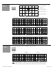
(4) Deep Without Row 1 (5) Middle Without Row 1 (6) Limited Without Row 1