
User`s guide


75.5134.10 EN 20110519 Page 12 of 13
TROUBLE-
SHOOTING –
Cont.
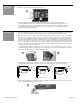
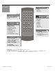
ACCESSORIES
PROBLEM PROBABLE CAUSE CORRECTIVE ACTION
1. Allow the door to open in the automatic
mode. Unlock the Bodyguard and launch a
setup by pressing the Setup key, followed
by the number 2. If the sensor does not
begin flashing green, and instead goes
back to a red indication, improper data
exists. Refer to respective lockout User’s
Guide for troubleshooting.
2. Check for proper polarity at terminal 6 and
7. The negative wire from the lockout
(white) should be connected to terminal 6,
and the red/white striped wire from the
lockout should connect at terminal 7.
HELPFUL HINT: If faulty data is suspected,
simply power the door to the open position
(by activation OR with the use of a hold
open switch). While the door is open,
unlock the Bodyguard, and press the setup
key, followed by the number 2. If the
sensor goes back to a red LED (as opposed
to flashing the green LED to indicate a
setup), there is a strong probability that the
data is incorrect. Refer then to the
respective lockout User’s Guide for
troubleshooting help.
Bodyguard repeatedly re-
learns the environment
with each door position.
1. Improper data from the lockout
device
2. Data polarity at the Bodyguard is
incorrect
Bodyguard not reacting to
the remote control
1. Batteries in the remote control are
dead.
2. Distance between sensor and
remote is too far.
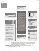
1. Replace batteries in the remote control
2. Move in closer to the sensor when
programming.
3. If remote control fails, manual programming
procedures may have to be used (See Pg. 8).
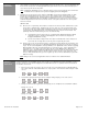
HELPFUL HINT: Use BEA’s Spotfinder to
test the output of the remote control. Simply
point the remote at the IR Spot on the
Spotfinder, press the Unlock key on the
remote, and red LED should illuminate.
BODYMOUNT
DP-HUB
(
ed
p
s
)
SPOTFINDER
LOCKOUT SAFETY
BEAM / SBK-30
BODYGUARD
Q
UICK DISCONNECT HARNESS
(
20.5128
)
BR3 INTERFACE MODULE