
User`s guide

75.5134.10 EN 20110519 Page 2 of 13
SAFETY
PRECAUTIONS
MECHANICAL
INSTALLATION -
PREPARATION
MECHANICAL
INSTALLATION –
PLACEMENT OF
THE SENSOR
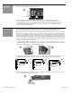
Wall Switch
Wall Switch
Bodyguard
Bodyguard
20” min
20” min
• Shut off all power going to the header before attempting any wiring procedures.
• Maintain a clean & safe environment when working in public areas.
• Constantly be aware of pedestrian traffic around the door area.
• Always stop pedestrian traffic through the doorway when performing testing that may result in unexpected
reactions by the door.
• Always check placement of all wiring and components before powering up to insure that moving door
parts will not catch any wires and cause damage to equipment.
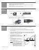
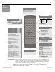
To prepare the Bodyguard for mounting to the header, perform the following:
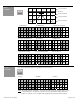
a) Remove both end caps from the Bodyguard (Picture 1). Each is attached by one Phillips head screw.
b) Remove both lenses from Bodyguard by simply sliding them out at each end (Picture 2).
c) Remove the center eye shield (Picture 3) (take care not to damage the light tube on the inner side of the
shield). Simply pull out from the top end and rotate out as shown below.
d) Slide the PCB out of the extrusion and set it aside (Picture 4).
Remember these guidelines when installing a Bodyguard:
The Bodyguard should be mounted at a height range of 6’ 6” to 8’. Maximum mounting height is 9’.
The Bodyguard should be mounted above the door on the swing side.
The Bodyguard shall be mounted flush with the bottom of the automatic door header. This is absolutely
necessary to allow the detection pattern to reach back through the threshold area when the bodyguard is
in the open door position.
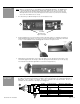
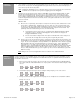
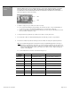
For SINGLE DOOR APPLICATIONS, the Bodyguard should be mounted at the center of the door opening.
However, if this is not possible, the unit may be installed off-center. In such cases, pattern location will have to
be altered for proper placement of the field of detection. Try to avoid mounting locations that may pose
potential problems such as directly over a door arm.
For DOUBLE-EGRESS APPLICATIONS, one
Bodyguard should be mounted over each swing-path.
There should be at least 40” of separation between the 2
Bodyguards when measured between the centerline of
each sensor.
If the Bodyguard sensor is the only sensor being used
for safety at the swing side of the door, to be in
compliance with ANSI 156.10, a lockout safety beam or
door mounted safety side Superscan(s) is needed in
addition to the Bodyguard sensor.
CAUTION
: FOR ALL APPLICATIONS, REFER TO THE
PATTERN CHARTS FOR WIDTH AND
DEPTH IN THE APPLICABLE SECTION OF
THIS GUIDE. PATTERNS SHALL BE
ADJUSTED TO ACHIEVE MAXIMUM
DETECTION ZONES, AND SHALL BE IN
COMPLIANCE WITH ALL APPLICABLE
SAFETY STANDARDS (I.E. ANSI A156.10).
1 2
3
4