
User`s guide

75.5134.10 EN 20110519 Page 3 of 13
ELECTRICAL
INSTALLATION
AND CABLING
MECHANICAL
INSTALLATION
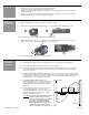
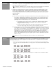
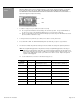
1. The extrusion has pre-drilled mounting holes at each end (Pictures 5 & 6).
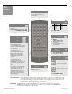
2. Hold the Bodyguard up to the pre-determined location, and attach using the 2 self-drilling screws that are
included with the package (Picture 7). It may be necessary to pre-drill a pilot hole (Picture 8) in the header
for ease of screw installation. Ensure that Bodyguard is mounted securely at each end.
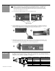
3. If Bodyguard is mounted directly to door header, and cabling is to pass directly into header, drill a ¼” hole
next to the Bodyguard’s left side end cap to allow wire passage into header (Picture 9). The wire passage
hole should be in a location that aligns with the cut out in the end cap (Picture 9).
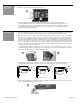
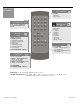
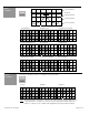
1. Once the Bodyguard is securely attached to header, cabling & wiring may be completed. Wire the 7-pin terminal
block OR use the cable that is provided for use with the 10-pin connector (Picture 10). If wiring the Bodyguard to a
BEA module, such as an LO-21 or an MC15. Refer to the schematic for the respective module. For ease of
installation, wire the terminal before attaching it to the Bodyguard.
Position Connection 7-Pin Wire Color (10-pin cable)
1 12 to 24 V AC / DC
+/- 10%
Red
2 24 to 24 V AC / DC
+/- 10%
Black
3 Common White
4 Normally Open Green
5 Normally Closed
6 Data - Brown
7 Data + Blue
2 PWR
4 NO
6 IN -
1 PWR
3 COM
5 NC
7 IN +
BLACK
RED
WHITE
GREEN
BROWN
BLUE
10 PIN
10 PIN
NOTE: BEA, Inc. recommends the use of a BodyMount for most Bodyguard applications. The BodyMount is a
3” standoff that allows the Bodyguard to be slightly distanced from the face of the closed door. This
helps to prevent ghosting caused by slight door movement while closed, and also prevents ghosting
when SuperScan sensors are used (as the SuperScan extrusions at the top of the door are extremely
close to the sensor while the door is closed
)
.
Pre Drilled
Mounting Holes
Approx. 9 ¾” Apart
5
6
7
8
9
10