
User`s guide

75.5134.10 EN 20110519 Page 4 of 13
MECHANICAL
ADJUSTMENTS
ELECTRICAL
INSTALLATION
AND CABLING
(Continued)
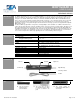
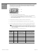
2. Attach the terminal block to the Bodyguard (Picture 11).
3. With the terminal block attached to the Bodyguard, feed the opposite end of the cable through the
previously drilled wire passage hole, and on into the header. Pull the cable all the way through and route it
to the location of the automatic door control. Refer to the respective User’s Guide for the BEA product you
are interfacing with. Ensure a dedicated power source of 12 or 24 V AC / DC +/- 10% (BEA PN: 1024VAC
may be used for powering this product).
1. Once all installation, wiring and cabling procedures have been completed, mechanical adjustments can be made.
Please note that further adjustments may be required after powering and walk testing the detection field.
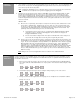
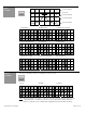
2. Aside from placement on the header, the only mechanical adjustment that may be made to the sensor is the angle
adjustment. The Bodyguard is factory pre-set to the +5º position, but may be reduced to a 0º position or increased
to a 10º position. The greater the angle, the farther from the door the pattern will be. The 0º angle should only be
used when the Bodyguard is mounted to a BodyMount block or to a soffett above the door that extends out from
the face of the safety side of the door – in this case, the 0º setting would improve the location of the detection field
across the threshold area of the doorway. It is recommended that for most applications, the unit be powered and
walk tested at the pre-set 5º angle. After walk testing, if the detection field needs to be changed, then proceed with
changes to the angle setting as shown below.
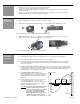
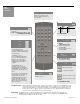
3. To change the angle setting the end caps, lenses, and center eye shield must be removed (as shown on page 2).
The terminal block must also be removed if it has been wired. Once removed release the white clips, as shown
below, and rotate outward to remove the PCB (Pictures 12 & 13).
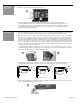
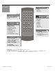
4. Once the PCB is completely removed from the housing, the angle position may be changed. There are two clips
per Bodyguard and the angle must match for each clip on the same PCB. The positions are shown below.
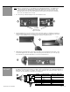
5. Slide the left and right lens back into place (Picture 14) and proceed with power-up procedures. Leave the end
caps off until all final adjustments have been made.
11
0°
10°
5°
12 13
14
Factor
y
Default