
User`s guide

75.5134.10 EN 20110519 Page 5 of 13
DUEL EGREES:
REDUCING
CROSS TALK
POWER-UP
PROCEDURES
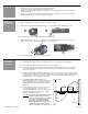
1. Upon completion of mechanical and electrical installation, apply 12 to 24 V AC / DC +/- 10% to the Bodyguard, with
the door in the closed position. The Bodyguard will flash a green LED at a rate of 2 Hz, then it will expire upon a
successful set-up in the door-closed position.
NOTE
: If applying the Bodyguard to a door control that requires a learn cycle upon powering, it is recommended
to allow the doors to complete a learn cycle before applying power to the Bodyguard.
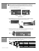
2. Activate the door to the full open position. When used with BEA’s lockout relay, the Bodyguard will once again
flash the green LED and will execute a door-open set-up. Upon completion of the set-up for the door-open
position, the doors will begin closing. Normal operation should resume thereafter. Proceed with fine-tuning to
insure compliance with all applicable safety standards (i.e. ANSI A156.10). If set-up is unsuccessful, refer to the
Troubleshooting Guide at the end of this Users Guide, and also to the guide located at the end of the respective
lockout User’s Guide.
HELPFUL HINT:
#1: Once the sensor is powered up, and completes a setup for the closed door position, activate the door to the
open position as indicated above. During this first open cycle, if the sensor does not begin to flash green
once the door is full open, a data problem is highly likely. If the door went open and the sensor just stayed
red, in detection, it probably did not get the correct data signal from the respective lockout module. As a
preliminary check to the troubleshooting, be sure to check the following:
a) The white wire from the lockout needs to go to terminal 6 at the Bodyguard, AND the red/white
striped wire needs to go terminal 7 at the Bodyguard. If these two wires are swapped, the
Bodyguard will NOT work correctly.
b) Check to ensure that the voltage from the motor (at the red and black wire of the lockout) has at
least 10 volts DC. A voltage that is too low may not be recognized by the lockout.
#2: If the door goes to the open position and a setup is completed successfully, but then the door begins to close
and immediately recycles open, it is possible that the Bodyguard’s detection of the closing door is causing a
recycle. Be sure to check dipswitch 6, if using an LO21B, U, or P: dipswitch #6 on these modules is typically
ON for applications where the red and the black wire are connected to a motor. In these applications the
lockout expects to see a voltage on these wires when the door is in the OPEN position. Only specific
applications, such as a Besam Swingmaster MP (with CUP control) may require the switch to be in the OFF
position. Additionally, always make sure that the red wire from the lockout goes to the positive leg of the
motor (or switch) and the black wire goes to the negative leg. If these wires are backwards, the system will
NOT work correctly.
NOTE
: Always be sure to refer to the applicable lockout User’s Guide for more detailed information.
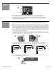
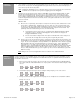
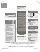
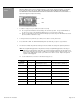
Perform the following set up using BEA’s remote control to reduce cross talk between duel egress applications. Refer to
the figure on page 2 to ensure the two Bodyguards are installed with at least 40” of separation when measured between
the centerline of each sensor.
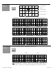
1. Place doors in the hold open position. Unlock sensor and set open door Pattern Depth to 5 (Medium Pattern).
This sequence will turn off threshold IR while door is in open position. This function should be changed on both
sensors:
+ + then +
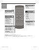
2. The infrared frequency function may need to be changed. Change frequency on one of the sensors:
+ + then +
3. Change to a different mode in applications where high gloss floors or multiple doors are installed in vestibules.
Change sensor one to:
+ + then +
Change sensor two to:
+ + then +