Owner’s Manual Actual product appearance and functionality may vary from photographs, illustrations and descriptions included in this manual.
table of contents Disclaimers. . . . . . . . . . . . . . . . . . . . . . . . . . . . . . . . . . . . . . . . . . . . . . . . . . . . . . . . . . . . . . . . . . . . . . . . . . . . . . . . 1-2 Parts List . . . . . . . . . . . . . . . . . . . . . . . . . . . . . . . . . . . . . . . . . . . . . . . . . . . . . . . . . . . . . . . . . . . . . . . . . . . . . . . . . . . 3 Base and Remote Overview . . . . . . . . . . . . . . . . . . . . . . . . . . . . . . . . . . . . . . . . . . . . . . . . . . . . . . . . .
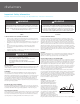
disclaimers Important Safety Information Read all instructions before using your adjustable base. Save these instructions. WARNING WARNING Always unplug the base from the electrical outlet before servicing any part of the base. To reduce risk of electric shock, unplug the base before cleaning. To safely disconnect, ensure the base is in a flat position with all motors off, and unplug from power source. For optimal safety and operation, plug bed base into a surge protector (not included).
disclaimers the mattress support platform shall be ± 3°, which translates to a tolerance of up to 1 ½”. The angle (designated “B” in figure 1) between the flat section and foot section for various configurations of the mattress support platform shall be ± 3°, which translates to a tolerance of up to ¾”. Any adjustable foundation deemed to be within these allocated tolerances is considered to have met the manufacturer’s quality control standards.
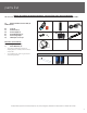
parts list Before discarding the packing materials- ensure all the parts are accounted for. All electronics and components that need to be installed are located in boxes under the base or attached to the frame.
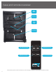
base and remote overview Head Motor Control Box Power Down Box Foot Motor 4 Lifts and Lowers Head Lifts and Lowers Foot FLAT Preset Position Zero-G Preset Position Actual product appearance and functionality may vary from photographs, illustrations and descriptions included in this manual.
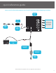
quick reference guide Not to scale. For illustration purposes only. Read all instructions before beginning installation. Control Box Power Supply Power Cord Connection ports to head and foot motors installed under the base. Input Power Cord Power Down Box Sleeptracker® Sensor(s)* Sleeptracker® Processor Power Cord *Queen/Full has two Sleeptracker Sensors. See page 16 for setup instructions.
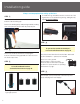
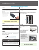
installation guide Always use two people when setting up the base STEP 1 Place the bed base box in a desired location with the bottom of the box facing up. To install the legs, thread the washer over the bolt of the leg with the recessed side facing the leg, and tighten by hand. Do not over tighten. Remove the binding straps and packing materials, making sure not to puncture the box with any sharp objects.
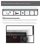
installation guide Always use two people when setting up the base STEP 6 STEP 9 Uncoil the Power Cord and connect to the Power Supply. Place Power Supply on the ground and extend from the base. Ensure batteries are correctly installed in the back of the remote. Ensure that the Power Supply and all attached cords are directed toward the desired surge protector. Quickly test functions to verify proper setup before placing mattress on base. Press FLAT to return the base to a flat position.
headboard bracket installation guide (optional) A 9/16” (14 mm) & 1/2” (13 mm) socket and crescent wrench are necessary to complete installation. HEADBOARD BRACKET COMPONENTS Headboard Bracket (2) T-Bracket (2) Spacer (2) Long Bolt (8) Short Bolt (10) Nut (18) STEP 1 a.) Align the hole in the bracket to the brass sleeve into which the leg threads. Hold the bracket in place and screw the leg into the base until it is snug. DO NOT OVERTIGHTEN. Too much force may cause the leg to spin freely.
headboard bracket installation guide (optional) STEP 2 Attach the plastic spacer and T-Bracket. a.) M easure the distance between the mounting holes on the headboard and install the spacer and attachment plate to accommodate the headboard. b.) To install the plastic spacer and attachment plate, you will need (2) long bolts and (2) nuts. Place the spacer and attachment plate in the desired location and slip the bolts through the holes with the head of the bolt facing outward.
emergency power down box Store the power down box in a convenient location for emergency use. (2) 9 Volt batteries are required to operate the power down feature and are NOT included. FOR EMERGENCY USE ONLY. In the event that the base is stuck in an articulated position during a power outagethe Power Down Box will return the base to a flat position. The Power Down Box can only be used to bring the base to a flat position.
pair remote The original remote that comes in the box is already paired to the bed base. No further action is required. In the event that the remote is not paired with the base, follow the steps below. STEP 1 STEP 3 Remove back cover from remote control. Remove and replace batteries. Press and hold button on the back of the remote. The light will begin to flash then become a continuous solid light. STEP 2 STEP 4 Double click the button on the Power Down Box (this will not cause the base to move).
setting up two bases Connecting straps are secured to the base frame upon delivery. If a split setup is being installed, plastic connecting straps are provided (one per base) to secure the bases together. Use both straps to secure the head and foot portions together. STEP 1 With the bases in their desired location, slightly loosen both legs to allow the strap to fit on the leg bolt, between the leg washer and frame. STEP 2 Slide side (a) of the connecting strap onto leg bolt.
syncing two bases If simultaneous operation of two bases is desired, use the SmartSync™ Cord to connect the electronics of both bases together. Connect each power-down box male connection to the sync cord female connection (Refer to the illustration below). STEP 2 STEP 5 Disconnect the power-down box cable from each control box. Make note where the cable was plugged in. Plug base back into the power source. STEP 3 STEP 6 Connect the male end of the sync cord to each control box.
Sleeptracker® setup PART LIST *King bases will have a spare processor and 5v DC Power Please refer to Beautyrest Quick Start Guide for Sleeptracker® download and setup instructions. Visit help.beautyrest.com from your smartphone to download the app and view additional Sleeptracker® product information.
troubleshooting If one or more functions on the bed base have stopped operating: • Check under the bed base to verify that the wired connections are secure and that there are no cords or bedding obstructing the movement of the base. • Check to ensure the green LED light is illuminated on the control box. If there is no light, verify that the input and power cords are properly connected. • Unplug the base for 1 hour to reset the electronic components.
español PG 1-2 Sobre las precauciones y el uso: Atención: Restricciones importantes sobre la seguridad Lea todas las instrucciones antes de usar su base ajustable. Guarde estas instrucciones. ADVERTENCIA • Mantenga la cama en posición plana cuando no esté en uso. • Manténgase alejado de las piezas móviles mientras está en movimiento. • Antes de ajustar , asegúrese de que los niños y las mascotas estén alejadas de las partes móviles y no están bajo somier antes de ajustar.
español TOLERANCIA Todas las bases ajustables Ergomotion, dependiendo de la marca y el modelo, están diseñados y fabricados para realizar y funcionar dentro de los parámetros de control de calidad designados. Las bases están sujetas a inspecciones minuciosas y rigurosas durante el proceso de control de calidad para asegurarse que las bases operen dentro de estas normas durante el uso normal de funcionamiento.
español digital de Clase B, cumpliendo con la Parte 15 de las Reglas de la FCC. Estos límites están diseñados para proporcionar protección razonable contra interferencias perjudiciales en una instalación residencial. Este equipo genera, utiliza y puede irradiar energía de radiofrecuencia. Si no se instala y emplea este equipo de acuerdo con las instrucciones, el equipo podría causar interferencias perjudiciales a las radiocomunicaciones.
español Control Box = Caja de control Power Cord = Cable de electricidad Power Supply = Fuente de energía Input Power Cord = Cable de entrada de electricidad Power Down Box = Generador de corriente Connection ports to head and foot motors Installed under the base. Puertos de conexión a todos los motores de la cabacera y motores de la pies (instalados debajo de la base) • • • • • CABEZA PIES ENCENDIDO/APAGADO MULTIFUNCIÓN REAJUSTAR Pg.
español PASO 2: Presione y sostenga el botón hasta que la base esté en posición horizontal. Nota: La luz roja se apagará después de varios minutos. Pero podrá presionar el botón en cualquier momento del apagón para hacer que la base regrese a la posición horizontal. Sólo para casos de emergencia. El generador auxiliar de corriente sólo debe usarse para hacer que la base regrese a la posición horizontal. Esto no ocurrirá si la base está conectada a una fuente de corriente activa. Pg.
français Pg. 1-2 - Précautions de sécurité et déclarations d’utilisation AVERTISSEMENT • Gardez lit en position à plat lorsqu’il ne sert pas. • Restez à l’écart des pièces mobiles en mouvement. • Avant de régler , assurez-vous que les enfants et les animaux sont clairement de pièces mobiles et ne sont pas sous la base du lit avant de régler. • Ne pas laisser les enfants utiliser la base de lit sans supervision d’un adulte .
français tours par minute augmente, les vibrations changent simultanément. TOLÉRANCE Tous les sommiers ajustables Ergomotion, selon leur marque et modèle, sont conçus et fabriqués pour fonctionner selon des paramètres précis de contrôle de qualité. Les sommiers sont sujets aux inspections méticuleuses et rigoureuses pendant notre processus de contrôle de qualité pour nous assurer que les sommiers fonctionneront selon les normes exigées lors d’un usage normal.
français accepter toute interférence qui pourrait causer un mauvais fonctionnement. Interférence Radio et de la Télévision IC: 20700-STS10 Cet appareil a été testé et jugé conforme aux limites d’un dispositif numérique de Classe B, conformément à la Partie 15 des règles de la FCC. Ces limites sont conçues pour fournir une protection raisonnable contre les interférences nuisibles dans une installation résidentielle. Cet appareil génère, utilise et peut émettre de l’énergie radiofréquence (RF).
français 2 3 4 5 6 7 PIED VIBRATION DE LA PIED VIBRATION DE LA TÊTE ÉNERGIE MULTIFONCTION REMETTRE EN PLACE Télécommande: Vue d’ensemble de la télécommande Lifts and Lowers Foot = Soulève et Baisse des pieds. Zero-G Preset Position = Zéro-G® Position préréglée Lift and Lowers Head= Soulève et Baisse Tête Flat Preset Position= Allongé Position préréglée – Position Droite Pg.
français Attention: la lumière rouge s’éteindra après quelques minutes, cependant, le bouton peut être poussé à tout moment pendant la coupure d’électricité pour retourner le lit dans la position droite. Au cas d’émergence: La boîte pour s’éteindre peut être utilisée seulement pour retourner le lit dans la position droite. Cette boîte ne retournera pas le lit dans la position droite quand la base est encore branchée dans une prise en état de marche. Pg.
Use barcode to sync Sleeptracker® app. ©2015 Ergomotion Inc US/Canada Customer Service Phone Fax Email Web 1-888-550-3746 805-979-9399 info@ergomotion.com www.ergomotion.