
Manual

5
CF1000 Burner Manual
Pre-installation Checklist
Combustion Air Supply
The burner requires combustion air and ventilation
air for reliable operation. Assure that the building
and/or combustion air openings comply with National
Fire Protection Standard for Oil-Burning Equipment,
NFPA 31.
For appliance/burner units in confi ned spaces, the
room must have an air opening near the top of the
room plus one near the fl oor, each with a free area
at least one square inch per 1,000 Btu/hr input of all
fuel burning equipment in the room.
For other conditions, refer to NFPA 31 (CSA B1139-
M91 in Canada). If there is a risk of the space being
under negative pressure or of exhaust fans or
other devices depleting available air for combustion
and ventilation, the appliance/burner should be
installed in an isolated room provided with outside
combustion air.
Clearances
With the burner installed in the appliance, there
must be adequate space in front of and on the
sides of the burner to allow access and operation.
Verify that the clearance dimensions comply with all
local codes and with the appliance manufacturer’s
recommendations.
Fuel Supply
○
○
○
○
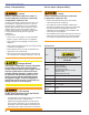
Adequate Combustion and
Ventilation Air Supply Required
Failure to provide adequate air supply could result
in asphyxiation, explosion or fi re hazards.
The burner cannot properly burn the fuel if it is not
supplied with a reliable combustion air source.
Follow the guidelines in the latest editions of the FPA
31 and CSA-B139 regarding providing adequate air
for combustion and ventilation.
y
y
Oil Supply Pressure
Control Required
Damage to the fi lter or pump seals could cause
oil leakage and a fi re hazard.
The oil supply inlet pressure to the burner cannot
exceed 3 psig.
Do not install valves in return line.
Insure that a pressure limiting device is installed in
accordance with the latest edition of NFPA 31.
Gravity Feed Systems: Always install an antisiphon
valve in the oil supply line or a solenoid valve (RWB
Part # 21789) in the pump/nozzle discharge tubing
to provide backup oil fl ow cut-off protection.
y
y
y
y
The fuel supply piping and tank must provide #1 or
#2 fuel oil at pressure or vacuum conditions suitable
for the fuel unit (oil pump) on the burner. Refer to
fuel unit literature in the literature envelope in the
burner carton to verify allowable suction pressure.
If fuel supply is level with or higher than fuel unit -
When the fuel unit is not required to lift the oil, the
installation is usually suitable for either a one-pipe or
two-pipe oil system. The oil pressure at the inlet of
the fuel unit must not exceed 3 psig.
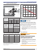
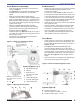
See Figure 9 for one-pipe fuel supply installations.
See Figure 10 for two-pipe fuel supply installations.
If fuel supply is below the fuel unit -
Use a two-pipe oil system when the fuel unit must
lift the oil more than 8 feet, The return line provided
by the two-pipe system is needed to purge the air
from the fuel lines and minimize the likelihood of air-
related problems during operation.
Nozzle Pressure
○
○
○
○
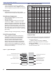
For typical nozzle fl ow rates at various pressures refer to
Table 1.
The fuel unit nozzle port pressure is factory set at
300 psig. Some original equipment manufacturer
burner applications may call for a lower pressure
to obtain a required fi ring rate. Do not change this
pressure unless directed to do so by the appliance
manufacturer.
○
Correct Nozzle and Flow
Rate Required
Incorrect nozzles and fl ow rates could
result in impaired combustion, under-
fi ring, over-fi ring, sooting, puff-back of
hot gases, smoke and potential fi re or
asphyxiation hazards.
Use only nozzles having the brand, fl ow rate (gph),
spray angle and pattern specifi ed by the appliance
manufacturer.
Follow the appliance manufacturer’s specifi cations
for the required pump outlet pressure for the nozzle,
since this affects the fl ow rate.
Nozzle manufacturers calibrate nozzle fl ow rates at
100 psig.
This burner utilizes pressures higher than 100 psig,
so the actual nozzle fl ow rate will be greater than the
gph stamped on the nozzle body. (Example: A 8.00
gph nozzle at 150 psig = 9.80 gph and at 300 psig =
13.86 gph)
y
y
Section: Pre-installation Checklist