
Manual

7
CF1000 Burner Manual
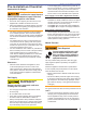
Firing Rate
Minimum Dimensions
(refractory-lined) (wet-base boilers)
HLHL
0 to 5 gph 7.0” 25.0” 7.0” 25.0”
5 to 10 gph 8.0” 35.0” 8.0” 40.0”
Table 2 -
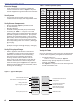
Air Tube Capacity (GPH) vs. Firebox Pressure
Firebox Pressure
(In W.C.)
No Reserve Air
10%Turndown
(GPH)
0.0 11.0 10.00
0.2 10.5 9.45
0.4 10.1 9.10
0.6 9.6 8.64
0.8 9.2 8.30
1.0 8.7 7.83
Note: 10% turndown indicates suffi cient reserve air to reduce
the CO
2
in the fl ue to 90% of its value.
Note: The above ratings may vary 5% due to variations in
actual job conditions.
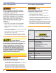
Stray Light
Protect Against Stray Light Lockout. Failure to follow
these instructions could cause loss of burner operation
resulting in no heat, an unplanned process interruption,
work stoppage and the potential for frozen plumbing or
other cold weather property damage.
The control must detect a dark, no-fl ame condition
in order to start the burner or it will hold in the stray
light lockout mode.
Shield the burner view window from direct exposure
to intense light.
○
○
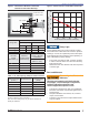
Air Tube
Length
(Dimension T)
Minimum
Insertion Depth
(Dimension E)
A.T.C. Codes
(A.T.C. = Air Tube
Combination)
Tube A
(Dim. D = 5.5”)
06.75” 2.94” CF66KD
10.25” 2.94” CF102KD
13.75” 2.94” CF136KD
17.75” 2.94” CF176KD
Dust and Moisture
Protect Against Dust and
Moisture
Wet, dusty environments could lead to blocked
air passages, corrosion damage to components,
impaired combustion performance and
result in asphyxiation, explosion or fi re.
This burner is designed for clean, dry installations.
Electrical controls are not protected against rain or
sprayed water.
Keep the installation clear of dust, dirt, corrosive
vapors, and moisture.
Protective covers and more frequent maintenance
may be required.
○
○
○
○
Section: Pre-installation Checklist
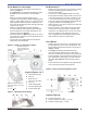
Figure 2 - Dimensions: Minimum Combustion
Chamber and Air Tube Mounting.
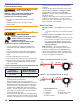
Figure 3 - Firebox Pressure: CF1000 with no Reserve Air
0.2 0.4 0.6 0.8
1.0
0.0
12
11
10
9
Firebox Pressure in Inches Water Column (W.C.)
Maximum Firing Rate U.S. GPH
KD
13
14
15
* Install burner with
2° pitch as shown.
*2°
H
L
T
D
E
1/4” ± 1/8”